The Control objects for a Designer process flow are:
- Join Object
- Junction Object
- Decision Switch
Object
- Decision Test
Object
- Set Object
- Synch Object
- Debug Object
The following sections describe how to define each Control object
as you include it in a process flow.
x
The Join object combines two or more documents into a single
document. The single document then proceeds to the next object in
the process flow. For example, if you have two XML documents;
A:
<A> ... </A>
and B:
<B> ... </B>
The Join object creates the following output:
<JOIN>
   <A>
    .
    .
    .
  </A>
  <B>
    .
    .
    .
  </B>
</JOIN>
Caution: Use caution when mixing Join and Junction objects
in a process flow. When a Join object is located after a Junction
object, results can be unpredictable.
The following image shows the Join object icon.

When you add a Join object to the flow, the New Join Object dialog
box opens, as shown in the following image.
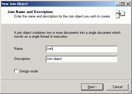
Type a name to identify the Join object in your process flow
and type a brief description (optional). The Design mode option
allows you to include the object in the process flow as a place
marker, that is, without defining its parameters. Click Next to
continue configuring the object.
The New Join Object - Properties dialog box opens, as shown in
the following image.
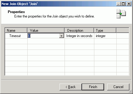
Timeout is the time period (in seconds) that the Join object
will wait to receive the documents it must join. The timeout count
begins when the first document enters the Join object. If it receives
all of the documents before the timeout period, the join process continues
without further waiting. If all documents needed to satisfy the
join are note received, then a status document is generated and
sent along the OnTimeout edge.
Select a Timeout value from the Value drop-down list and click Finish.
The Join object icon appears in the workspace.
x
A Junction object joins two or more paths of execution into a
single path. It does not join documents that travel along the path.
For example, if you have five distinct paths that run to a certain
point and then all paths execute the same logic, use the Junction
object to consolidate the flow at the point of common execution.
Caution: Use caution when mixing Join and Junction objects
in a process flow. When a Join object is located after a Junction
object, results can be unpredictable.
The following image shows the Junction object icon.

When you add a Junction object to a flow, the New Junction Object
dialog box opens, as shown in the following image.

Type a name to identify the Junction object and type a brief
description (optional). The Design mode option allows you to include
the object in the process flow as a place marker. Click Finish.
The Junction object icon appears in the workspace.
Note: There are no parameters associated with the Junction object.
x
The Decision Switch object evaluates the contents of a document
or a variable and routes the document accordingly, similar to the
switch/case construct of other programming languages. The main difference
is that the document can match multiple cases simultaneously when
using an XPath switch expression. The following image shows the Decision
Switch object icon.

When you add a Decision Switch object to a flow, the New Switch
Object dialog box opens, as shown in the following image.
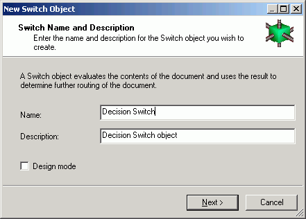
Type a name to identify the Decision Switch object and type a
brief description (optional). The Design mode option allows you
to include the object in the process flow as a place marker, that
is, without defining its parameters. Click Next to
continue configuring the object.
The Switch Expression dialog box opens, as shown in the following
image.
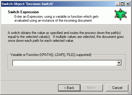
The Decision Switch object can direct the document down one or
more alternate paths based on the value of the switch expression.
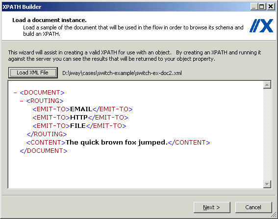
In the following example, the document contains a value indicating
the protocol(s) through which it should be routed (HTTP, EMAIL, FILE).
To accomplish this, an XPath is constructed to capture the switch
value from the document. You can also switch on computed conditions
by using a variable that has been set to one of your case values
earlier in the process flow. The following XML document has all
switch values represented for illustrative purposes.
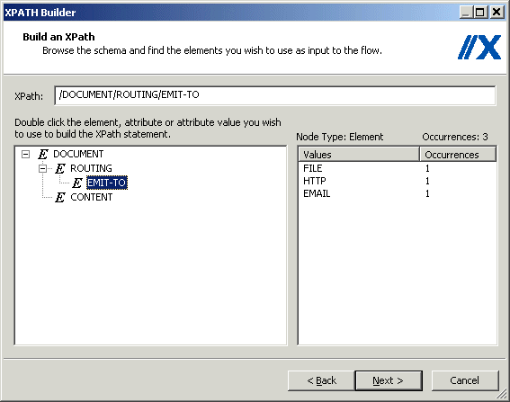
Click Next to continue and build the XPath
expression. For details, see Building XPath Statements. The following image shows the expression
in the XPath Builder.
When you are done constructing your XPath expression, click Next to
continue to the Switch Cases dialog box.
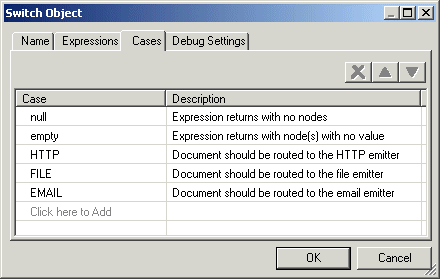
Add the Switch Case values and descriptions to the table. Each
switch case creates a named outlet leaving the Decision switch node.
When the current switch value is equal to a switch case, the document
will be sent down the corresponding edge for further processing. If
the XPath expression recovers multiple switch values, the document
will be sent down multiple edges simultaneously. See Building Relationships Between Objects for details on drawing edges that connect
to the named outlets of a Decision Switch Case. The following image
shows the Cases from a Decision Switch object properties window.
Click Finish. The Decision Switch object
icon appears in the workspace.
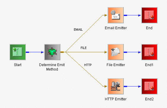
The following image shows the finished process flow containing
the Decision Switch example in this section.
x
The Decision Test object evaluates the contents of a document,
returns a true or false condition, and routes the document to the
next object(s) in the process based on that result. You will define
the evaluation and routing criteria through the Decision Test object properties.
The following image shows the Decision Test object icon.

When you add a Decision Test object to a flow, the New Test Object
dialog box opens, as shown in the following image.
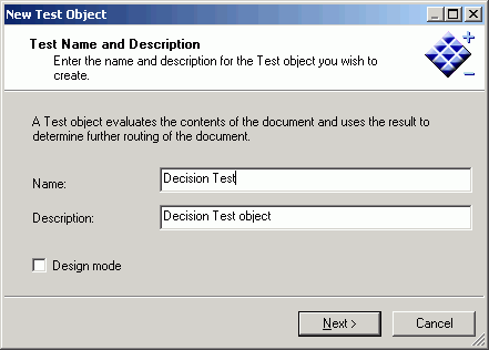
Type a name to identify the Decision Test object and type a brief
description (optional). The Design mode option allows you to include
the object in the process flow as a place marker, that is, without
defining its parameters. Click Next to continue
configuring the object.
The Test Operands dialog box opens, as shown in the following
image.
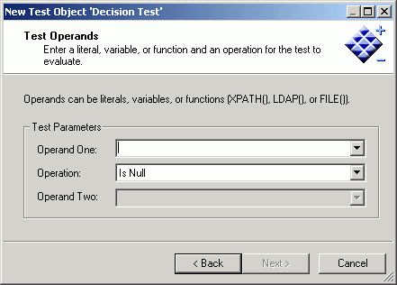
Operands in the Test Object can be literals, variables, or XPath
expressions. The available comparison operations are: Is Null, Not
Null, Equal To, Not Equal To, Greater Than, Less Than, Greater Than
or Equal to, Less Than or Equal to.
Select the test parameters and click Next.
The Value Occurrences dialog box opens, as shown in the following
image.
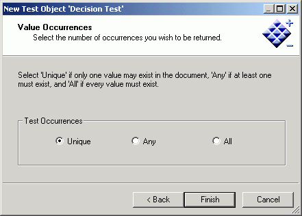
When using an XPath expression, many values can be retrieved
from the document. This dialog box allows you to specify how the
test comparison should handle multiple values.
Select a test occurrence. Unique means that only one value can
exist in the document. Any means that at least one value must exist
in the document. And All means that every value must exist in the
document.
Click Finish. The Decision Test object
icon appears in the workspace.
The Decision Test object has two pre-defined custom outlets,
‘true’ and ‘false’, from which you can draw edges. See Building Relationships Between Objects for details on drawing edges that connect
to the named outlets of a Decision Test case.
x
The Set object initiates one or more process events that Sync
objects are waiting on. Set and Sync objects are used to suspend
and resume the execution paths of a process flow.
The following image shows the Set object icon.

When you add a Set object to a flow, the New Set Object dialog
box opens, as shown in the following image.
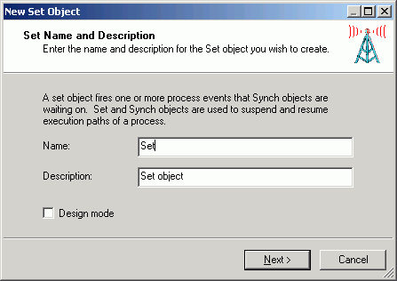
Type a name to identify the Set object and type a brief description
(optional). The Design mode option allows you to include the object
in the process flow as a place marker, that is, without defining
its parameters. Click Next to continue configuring
the object.
The Define Events dialog box opens, as shown in the following
image.
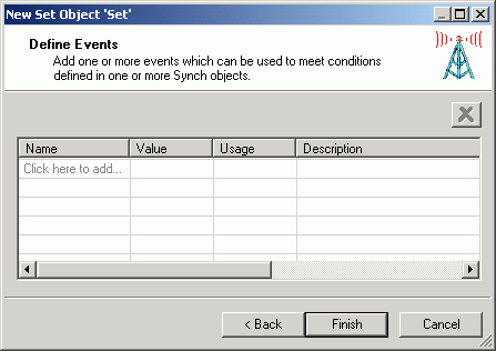
Add one or more events that can be used to meet conditions defined
in one or more Synch objects. Select Click here to add and
type an event name in the Name column, select a value and usage
from the Value and Usage drop-down lists, and type a description
of the event in the Description column.
When you finish defining the events, click Finish.
The Set object icon appears in the workspace.
x
Handling Header Information
Header information is "metadata" carried along with
the actual message payload, but it is not strictly a part of it.
Many protocols, such as HTTP, IBM WebSphere MQ, and JMS, provide
header information support, although often under names such as "user data"
or "side data."
The server makes received header information available in special
registers that take the name of the header field. For example, a
message received through HTTP will usually carry a header field
of “content-type,” which can be referenced as sreg("content-type"); these
registers carry the type of ‘header’.
When messages are emitted, special registers of type header are
associated with the message as appropriate to the protocol. To add
a special register of type header, the Set object can be used in
a process flow; set the register type to ‘header’.
The following image shows the Define Events dialog box (accessed
during the Set object configuration) that is defining an event named
MyHDR.
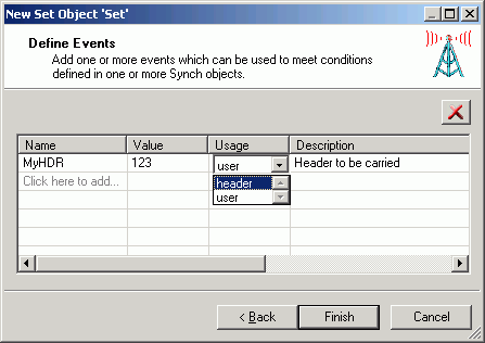
Because incoming headers are loaded into header special registers
and emitted message headers are drawn from such registers, this
provides a convenient method of transferring messages with headers
across protocols. However, the ultimate treatment of header information
is the responsibility of the application developer.
x
The Synch object waits for a condition to be met, such as the
expiration of a time limit or the evaluation of an expression as
'true'. The conditions are based on the events created through the
Set object.
The following image shows the Synch object icon.

When you add a Synch object to a flow, the New Synch Object dialog
box opens, as shown in the following image.
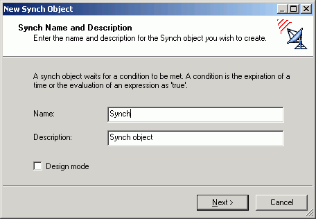
Type a name to identify the Synch object and type a brief description
(optional). The Design mode option allows you to include the object
in the process flow as a place marker, that is, without defining
its parameters. Click Next to continue configuring
the object. The Expression Builder dialog box opens, as shown in
the following image.
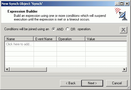
To build a Synch expression, click Click here to add.
The default Condition1 appears under the
Name column, as shown in the following image.
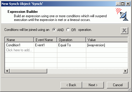
You can change the name and select the Event Name, Operation,
and Value for the new condition. The Event Name drop-down list consists
of the events defined in the process flow Set objects. Add as many
conditions as required. Above the condition parameters, select the
relationship between these conditions as an And or OR operation.
To delete a condition, select the condition and click the X above
the list of conditions.
Click Next. The Timeout dialog box opens,
as shown in the following image.
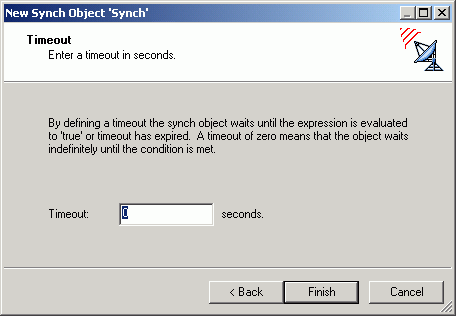
Type a timeout value (in seconds). This is the time period that
the Synch object will wait for the expression to be evaluated as
'true'. A value of zero (0) means that the Synch object will wait
indefinitely.
Click Finish. The Synch object icon appears
in the workspace.
x
The Debug object traces the state of the document in the process
flow. The following image shows the Debug object icon.
Note: This object has been deprecated because tracing
is now available on every object.

When you add a Debug object to a process flow, the New Debug
Object dialog box opens, as shown in the following image.
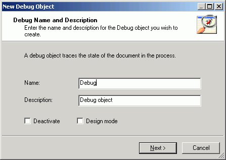
Type a name to identify the Debug object and type a brief description
(optional). The Deactivate option suppresses the function of the
object without removing it from the process flow, which is useful
for debugging. The Design mode option allows you to include the
object in the process flow as a place marker, that is, without defining
its parameters.
Click Next. The Properties dialog box
opens, as shown in the following image.
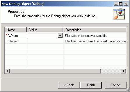
Enter the properties to define the Debug object, as follows:
- Where - directory
and file pattern of the trace file. For example, *.txt gives you
a file timestamp.txt. When you publish the
process flow you can activate the debug mode.
- Name - name
inserted in the trace file to uniquely identify the trace.
Click Finish. The Debug object icon appears
in the workspace.