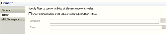
Working With the Mapping Builder

In this section:

When designing a Transform component, you must define the mapping rules and relationships between input and output documents, according to your requirements.

In iWay Transformer, the Mapping Builder is the user interface that enables you to graphically map your transformations. The following topics describe the mapping types and relationships that are supported for input and output documents and the mapping values that you can assign.

Mappings Tab

In this section:

The Mappings tab is the workspace and default display for designing a Transform component.

The following information is available on the Mappings tab:

The Mappings tab includes the following panes, which systematically display mapping-related information:

When working with structures, you can perform the following tasks:

The following menus let you easily perform various mapping-related tasks:

Input Node Workspace Menu

Right-click an input node in the workspace to display the menu options that are available for the nodes in the Input pane. You can expand or collapse various nodes within the structure tree, copy a node, and show or hide mappings between input and output nodes.

The following image shows the options available on the Input Node menu.

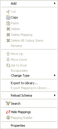
The following table describes the Input Node menu options.

Option

Description

Copy

Copies the selected input node and enables you to paste it in the output.

Reload Schema

Reloads the schema for the Input or Output structure pane.

Search

Opens the Search dialog box, enabling you to search for text or to search for and map input and output nodes.

Hide Mappings

Toggles between showing and hiding the mapping lines between the input and output structures.

Properties

Displays the properties of the selected input node.

Output Node Workspace Menu

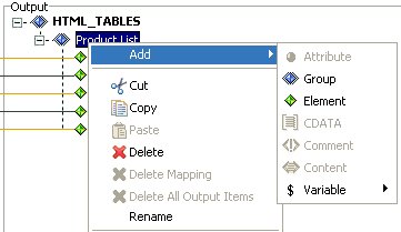
Right-click an output node in the workspace to display the menu options that are available for the nodes in the Output pane. The following image shows the options available on the Output Node menu.

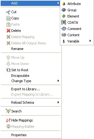
The options that are available on the Output Node menu depend on which node is currently selected in the Output pane.

You can disable certain options, depending on the type and position of the output node in the structure (for example, group, element, or attribute) or the data format (for example, XML or EDI X12).

The Add and Change Type option lists are dynamic. They also depend on the type of the output node and the output data format.

The following table describes the options available on the Output Node menu.

Option

Description

Add

Enables you to alter the existing output structure by inserting a new structure node of a specific type. The following types of structure nodes are supported:

  • Attribute (for XML format only)
  • Group
  • Element
  • CDATA (for XML format only)
  • Comment (for XML format only)
  • Content (for XML format only)
  • Variable
  • iWay XML Request

    (Available only when the output type is iWay XML Request.)

  • iWay Embedded XML Request

    (Available only when the output type is iWay Embedded XML Request.)

Refer to the Add submenu of a particular node for the list of enabled node types that you are permitted to add. The values of the available node types are enabled or disabled according to the mapping rules for the output data format. For example, if the XML data format is used, the only available types of nodes that you can add to an element type of node is an attribute node or a CDATA node.

Cut

Cuts the selected output node, making it available for the paste output operation.

Copy

Copies the selected node to a location that you determine.

Paste

Pastes the cut or copied node.

Delete

Removes a node from the Output structure. A confirmation dialog box is displayed for this option.

Delete Mapping

Deletes the selected mapping.

Delete All Output Items

Deletes all output items.

Rename

Renames the selected output structure node. This option is also available if you double-click the name of the node.

Move Up

Moves the selected node up the output structure tree, under the same parent node.

Move Down

Moves the selected node down the output structure tree, under the same parent node.

Set to Root

Enables you to represent the root of the document structure tree. This option is not available for record-based data formats, such as CSV. This option is available only for the nodes of type Group, because this is the only type of node that is permitted to perform the root functionality.

Encapsulate

Creates an invisible parent group wrapped around the output node that you choose to encapsulate. The encapsulating feature is useful when you are resolving complex looping or mapping issues. For an example, explore the WebFOCUS_Banklist sample transform project that is packaged with iWay Transformer.

Change Type

Changes the type of the node to one of the following:

  • Attribute
  • Group
  • Element
  • CDATA
  • Comment
  • Content

For more information, see Output Structure.

Export to Library

Exports the selected component to the library.

Export Mapping to Library

Exports the selected mapping to the library.

Reload Schema

Reloads the schema for the Input or Output structure pane.

Search

Opens the Search dialog box, enabling you to search for text or to search for and map input and output nodes.

Hide Mappings

Toggles between showing and hiding the mapping lines between the input and output nodes. The mappings signify the relationships between the input and output nodes, where the particular input value is used to construct the value of the output node.
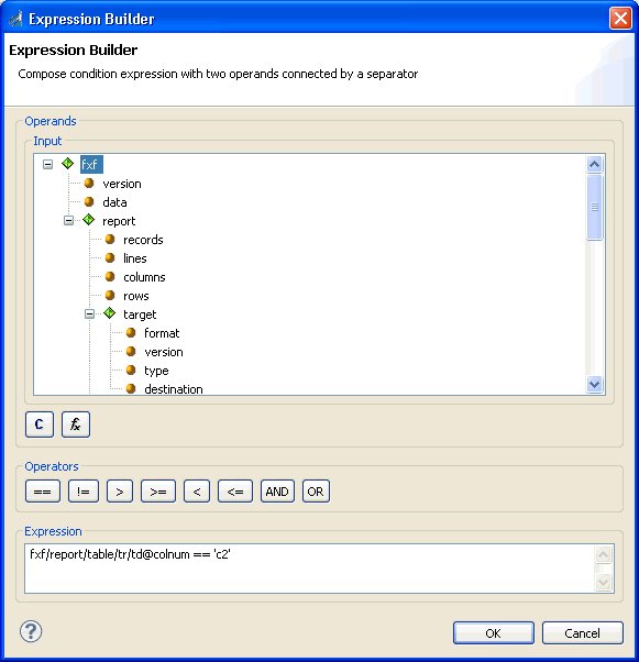
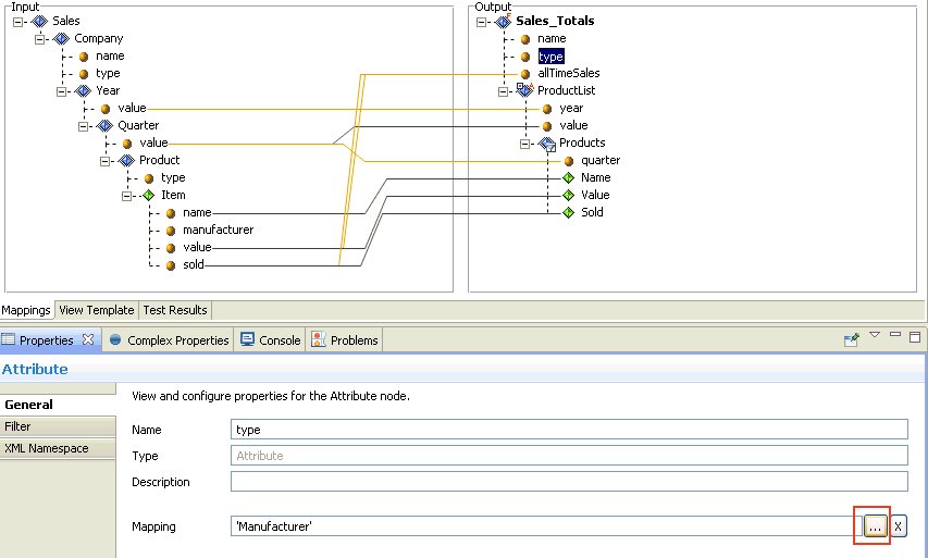
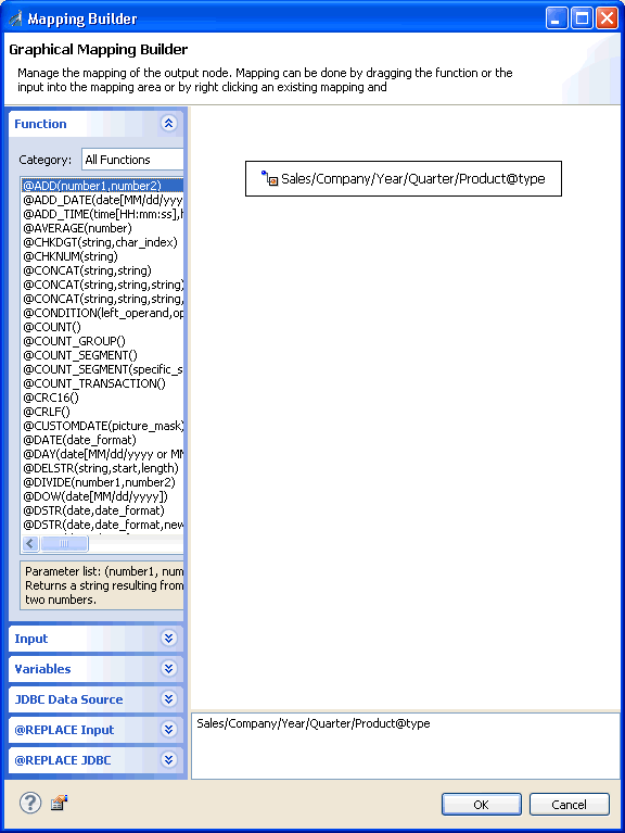
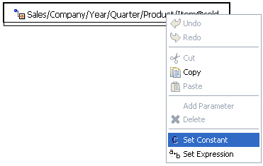
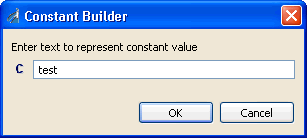
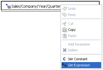
Mapping Builder

Opens the Mapping Builder window, which enables you to modify the mapping value by changing the input node that it maps to. Alternatively, you can add a function, constant, or expression to the existing mapping.

For more information on how to use the Mapping Builder, see Working With Functions.
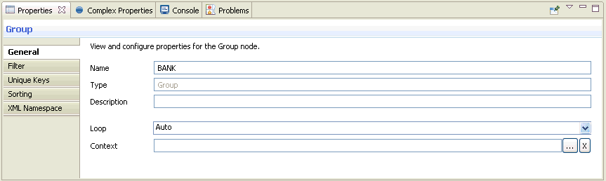
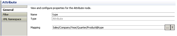
Properties

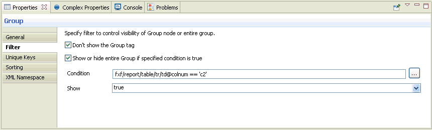
Displays the Properties tab, which shows the layout and structural information pertaining to the selected output node. For more information, see Group Properties.
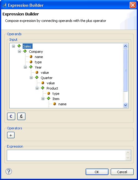
Input Structure

The input structure contains the input, which represents the groups, elements, and attributes encoded in the input document. Each node in this tree has exactly one parent, and can have more than one child.

The following table describes the various components provided in iWay Transformer to represent input nodes. Definitions of basic terms commonly used for nodes within an input document tree are also provided.

Input Document

The incoming document or message to which transformations apply. The following formats are supported:

The input document is displayed on the input pane as a visual representation of the input document tree. It maintains a logical order of component nodes, such as groups or elements, in relation to the underlying document, wrapping the nodes that are contained within other nodes. For more information, see the Input Document Tree Example that follows. Each input node contains a name that identifies the type of the node, optionally a number of attributes, or content.

Group

Block of data that has a group element as its root. It can contain other groups or elements nested within, as children. Multiple groups can also exist on the same level. A group was formerly called a parent.

iWay Transformer does not support mixed content group nodes containing data values. However, the group node for XML and HTML data formats can have any number of attribute nodes inside, if applicable.

Element

Usually belongs to the group as a leaf, which cannot have any other nested groups or elements. It typically stores a data value. In XML and HTML data formats, it can contain attribute nodes or CDATA.

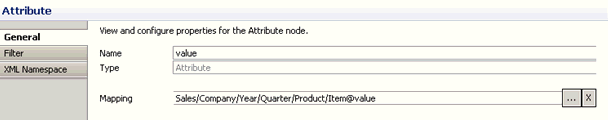
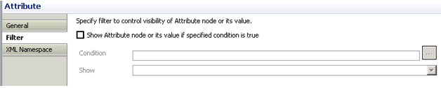
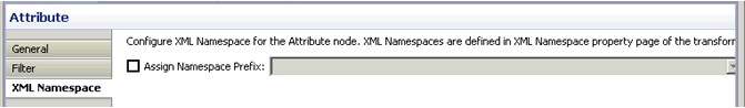
Attribute

Value associated with a group or element, consisting of a name, and an associated textual value. Attributes are used for XML and HTML data formats only. Each group or element can have zero to many attributes.

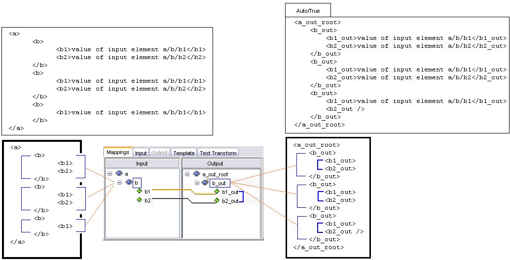
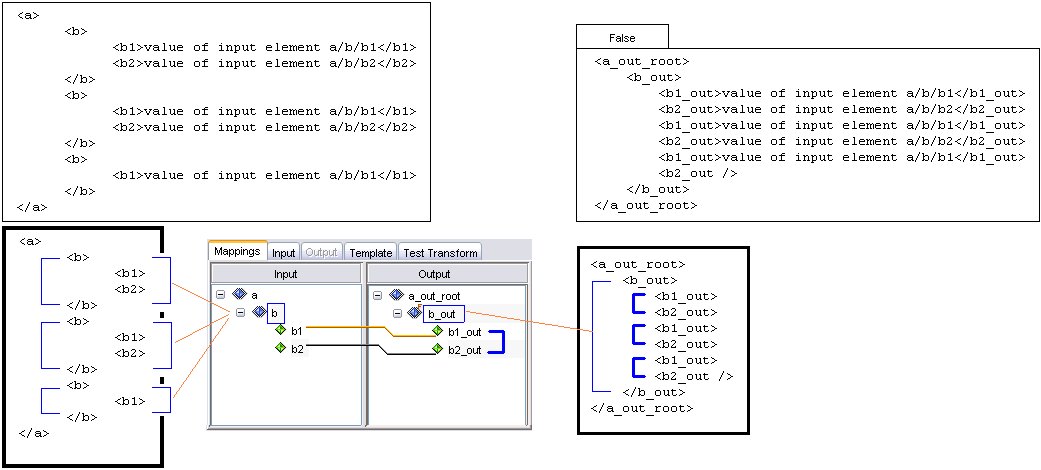
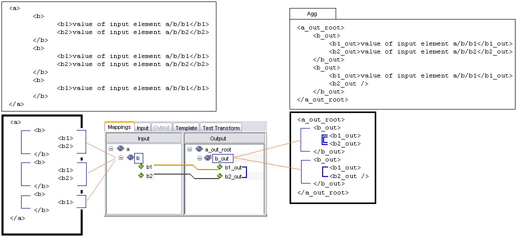
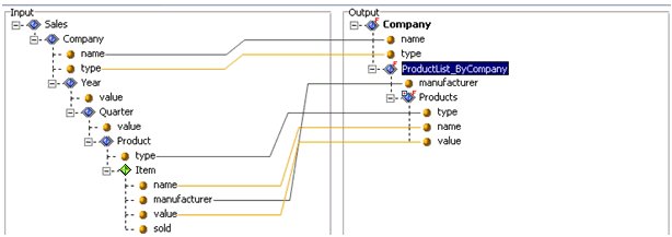
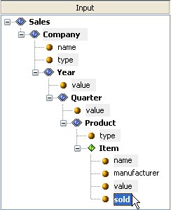
Example of Input Document Tree

Sample document tree of groups, elements, and attributes encoded in the input message. Each node in this tree has exactly one parent, and may have more than one child.

The following is a section of an XML input document:

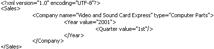
The following is a tree structure representation of the preceding XML:

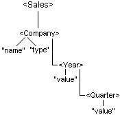
In iWay Transformer, the resulting input document tree is as follows:

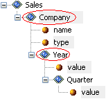
You can collapse or expand the document tree from the given node to its deepest descendant. iWay Transformer supports a set of different relationships that link nodes together.

The common types of document tree relationships are described in the following table.

Parent

The input can have more than one parent (root group). Parent is a group in relation to the elements or groups contained within it. In the preceding example, the group, Company, is a parent of two elements, Year and Quarter.

Child

Node A is called the child of node B, if and only if B is the parent of A. In the preceding example, the element Year is a child of the Company group.

Descendant

Node A is called a descendant of node B, if either (1) A is a child of B, or (2) A is the child of node C, which is a descendant of B.

Ancestor

Node A is called an ancestor of node B, if and only if B is a descendant of A.

Sibling

Node A is called a sibling of node B, if and only if B and A share the same parent. Node A is a preceding sibling if it comes before B in the input document tree. Node B is a following sibling if it comes after A in the input document tree.
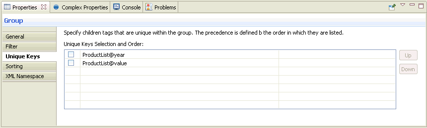
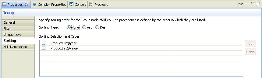
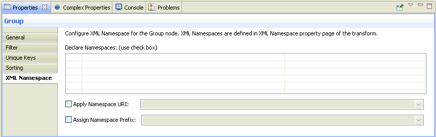
Output Structure

The output structure contains the output document tree, which represents the completed structure of groups, elements, and other supported node types, such as attributes or CDATA, encoded in the output document.

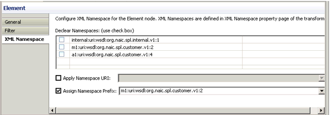
Each node in this tree has exactly one parent group. It can have one or more sibling nodes, unless it is the root node in the tree, which has to be unique according to the mapping rules in iWay Transformer. You can adjust the properties of the given node, such as visibility or namespace, to affect its appearance in the actual output document.

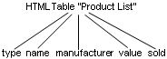
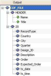
This topic examines the output document tree in the XML to HTML table example, which is included as a sample Transform component.

The output structure is represented as follows:

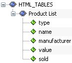
In iWay Transformer, the output document tree is visualized as follows in the Output pane of the Mappings tab:

Mapping Types

In this section:

The output document tree or hierarchy provides a graphical representation of how the output data will be organized. The output hierarchy defines output nodes line-by-line and uses a document tree structure to produce the desired output according to your requirements.

Nodes of type group and element typically serve as the primary building blocks for the output document tree, with the group type node at the root of the document tree, from which the rest of the structure is derived. Groups can have children and can be nested, which means that group nodes can be children and parents in relation to other group nodes.

Element nodes cannot have children, except in XML format, in which elements can contain XML-specific type nodes, such as attributes or CDATA items. Element nodes are always derived from the group node parent, which means that they are acting as leaves of the group branches.

Note: You can change the visibility of groups and elements or use predefined looping mechanisms to present your output data in the format specific to your requirements.

The following node types are supported in the Mapping Builder:

Adding New Output Nodes

One of the efficient methods for adding new output nodes is structure mapping. For more information about structure mapping, see Group. Another method of adding new output nodes is by building your document output tree from scratch, which is achieved by right-clicking an existing output node and selecting Add followed by the type of node you wish to add.

The supported types of the output nodes you may insert will depend on the type of the parent node to which you want to add your data nodes and can be driven by the context menu. For example, if you right-click an XML element node in your output structure, you may discover that the only possible type of nodes which can be added to that element node is an attribute node. By following these restrictions, the integrity of the output structure is maintained.

You can review the available options for the output node type by right-clicking the parent node and selecting the Add submenu.

Group

In this section:

A group is a block of data that has a group node as its root. It can contain other group or element nodes nested within, and other node types if supported (for example, attribute or CDATA for XML data format). Multiple groups can also exist on the same level. The nodes contained within a certain group are also called children of this particular group, sometimes referred to as a parent group in relation to the nodes nested within it.

Every output structure, regardless of the output data format, has at least one group node at its root. A group marks the start of an output block by specifying the start of an output loop. The first node in your output structure, referred to as a Root, is created automatically by iIT Transformer when you create your initial output structure. You can then build your structure from the root group node by adding the nodes of supported type one by one, or by copying the blocks of data from existing input or output structures. The output is produced by looping through the entire output structure (starting from the root group), one or more times (iterations), depending on your settings, while reading the mapped values from the input file.

Consider the CDF output structure displayed in the following image.

The first output node, CDF_FILE, is the first group node and is also called the Root. The presence of the Root node ensures that iIT Transformer loops over the entire output structure if needed. The next node in the output tree is a HEADER node, which is also a group type of node. Appearance of the HEADER node marks an output block of data, which includes the child element nodes Name and Title. The node, 20, is also a group node, which contains an output block of data to include the next ten child element nodes (RecordType to ts_time). Group nodes are distinguished by the Group icon, which has a blue diamond shape with a double border. Element nodes are distinguished by the Element icon, which has a blue diamond shape.

The following list contains the visual variations of the group node when a specific property is configured for it.

  • Invisible

    A group node that has its visible property set to false. This means that even though the group node is present in the output structure during design time, the invisible node’s value or the whole block of its children nodes will not be displayed in the run-time output produced by the project. For more information on hiding a group, see Filter Tab.

  • Context

    A group that has a context applied. The context property is the explicitly defined reference of the output group node to the particular input group node. It helps to control looping, and to resolve challenges and opportunities in the area of data structure searching. It is especially useful for nested multi-level repeated structures. It operates on the logical structure of the message (similar to XPath). It is available for use by any data format supported by iIT Transformer.

    To set the context property, right-click the group node b in the Output pane and select Properties. The Properties tab opens and displays the General tab by default.

    In the Context field, specify the path value for the looping node on the input side. Click the ellipses button, which opens the Input Fields pane. Select an input node to be mapped from the hierarchy tree and click OK.

    For more information on setting a context for a group, see General Tab.

  • Filter

    A group that has a filter applied. The filter property is useful when your incoming document data may contain loop iterations that should not appear in your output, according to your requirements. The filter property is designed to help you remove unnecessary blocks of data. For more information on specifying a filter for a group, see Filter Tab.

Depending on the group properties (loop, context, and filter) that are specified in the Properties tab for the selected output node, the group icon changes in the Output pane to reflect these settings. The following table lists all of these variations for your reference.

Group Setting

Visible Icon

Invisible Icon

Loop is set to true

Loop is set to false

Loop is set to aggregate

Context is applied and loop is true

Context is applied and loop is false

Context is applied and loop is aggregate

Filter is applied and loop is true

Filter is applied and loop is false

Filter is applied and loop is aggregate

Context and filter are applied and loop is true

Context and filter are applied and loop is false

Context and filter are applied and loop is aggregate

Additional XML Output Structures

In iIT Transformer, it is easy to create complex output structures for your output file. The way you arrange the nested components in the Output pane of the Mapping window is exactly how your output will be structured.

You can use parent nodes to create complex output structures with nested parent nodes and output loops for the XML output formats (XML and e-business). EDI (X12, HIPAA, EDIFACT, and SWIFT) output is treated as XML output due to the use of the e-business metadata by the Transformation Engine.

In addition to indicating the possible start of an output loop, a group node can also play an important role in building the following structures depending on the output data format:

  • XML output document - The first parent node value is defined as the root node of your XML output document. Other group nodes are defined as XML parent node names; they can be used to create nested loops for complex XML structures.
  • EDI (X12, HIPAA, EDIFACT, and SWIFT) output document - The group node for complex EDI messages can be used to create nested loops.

Group Properties

A set of useful properties is available for group output nodes. To view the properties for a group node, right-click the group node and select Properties. The Properties tab opens, as shown in the following image.

The General tab is displayed by default. Notice that the Type field contains a default value of Group, which indicates the type of mapping node being used. The properties of a group node are displayed in the following tabs:

  • General
  • Filter
  • Unique Keys
  • Sorting
  • XML Namespace

The following topics describe the tabs and options available from the Properties tab for the group node.

General Tab

In this section:

The General tab displays information such as the name and type of the node, as well as looping and context settings of the current node.

Looping

In order to determine how your group node will loop, you need to examine the list of available values from the Looping drop-down list, and select the applicable option.

  • Auto - Enforces the default looping mechanism. This is the default value of the Looping drop-down list.
  • True - Indicates that looping is necessary for the data in this group.
  • False - Indicates that the group node should not loop.
  • Agg - Indicates that looping should be aggregate.
    If aggregate looping is selected for the particular group, it means that all instances of this group node which have the same attribute values are combined into one unique group node. Any nodes that are children of these elements are also gathered and made subordinate to the new parent node.

Context

The Context field in the General tab is an advanced feature designed to help control local looping. Applying a context to a group node in your output structure can solve looping complexity issues. It is especially useful in projects, which require you to make references to input nodes located in different places within the hierarchy of a structure. The Context specifies the location of the node where the block of input that is being used for looping begins. Generally, this should be set to the innermost group block from your input structure, which encapsulates all of the input data that must be used within this output group node.

To better understand how the Context feature works, you can examine one of the iWay sample XML projects, located in the following directory:

<iWaySMHome>\tools\transformer\samples\transform_projects\xml\XML_to_XML\Context\Context.gxp

where:

<iWaySMHome>

Is the directory where iWay Service Manager was installed.

The input to output structure mapping is shown in the following image.

The input is an XML file that lists the details for the sales of a company item. The input information is organized by the year, quarter, product type, and the individual (brand). The output is an XML file containing the sales only for items from the specific manufacturer, for example, Cheapies. The output sales are arranged by year, quarter, and item.

Note that Product List has looping set to aggregate and context is set to Sales/Company/Year. Aggregation looping is required to enforce that only one parent node will exist in the output per each quarter. The reason why the context is set to Year is that the Year is the lowest group node in the input structure hierarchy that contains all of the information used within the Product List node. The input node Year opens the block of data in which the looping will occur.

When a context is applied to a group, the group icon in the Output pane is displayed as follows:

Filter Tab

The following image shows the Filter tab.

The Show or hide entire Group if specified condition is true check box enables you to control the appearance of all the nested groups and elements, by defining the condition and resulting action on the group node and its contents. Therefore, each individual output block produced by that output loop will be displayed or hidden in the actual output depending on the state of this option.

When a filter is applied, the group node icon in the Output pane is displayed as follows:

If this check box is selected and the Hide option is selected in the Action drop-down list, then the particular output block that satisfies the condition entered is omitted from being displayed in the output data.

When a group is hidden, the group icon in the Output pane is displayed as follows:

If the condition you enter is evaluated as true for an output loop and the Show option is selected from the Action drop-down list, then only that output block is displayed in the output. All other iterations of the group loop that do not match the condition you specified are suppressed from being displayed in the output data.

The condition you type must be in the following format:

For example:

Horses/Team/Years/Player/Goals == '30'

where:

Horses/Team/Years/Player/Goals

Is the location of the node in your input document structure.

30

Is the desired alphanumeric value of that node. As the incoming document is processed by the Transformation Engine, if this condition is met in the particular data iteration, the action selected in the Action drop-down list is performed.

If you are using the Expression Builder to construct the condition, click the icon to specify a constant value.

The following table lists the possible arguments (operators) for the block condition.

= =

equal to

!=

not equal to

>=

greater than or equal to

<=

less than or equal to

>

greater than

<

less than

When you click the ellipsis button next to the Condition field, the Expression Builder window is displayed to help you build a condition intuitively.

Unique Keys Tab

The following image shows the Unique Keys tab.

You can control the appearance of a group's output child nodes by defining nodes as unique in the Unique Keys tab. This will remove unnecessary data repetitions from your output group node. The child node you specify as the node will determine which loop repetitions will be suppressed. The output will display only the first unique occurrences of the key node. For example, assume that you generate the following non-unique XML output data:

<Product>
    <ProductID>XR281</ProductID>
    <Name>Green Rocket Vehicle</Name>
</Product>
<Product>
    <ProductID>SR71</ProductID>
    <Name>SR-71 Blackbird</Name>
</Product>
<Product>
    <ProductID>XR281</ProductID>
    <Name>Green Rocket Vehicle Again</Name>
</Product>

If you choose to make the output group node Product unique by specifying the output child node, ProductID, in the Unique Keys parent property, then your final output is the following:

<Product>
    <ProductID>SR71</ProductID>
    <Name>SR-71 Blackbird</Name>
</Product>
<Product>
    <ProductID>XR281</ProductID>
    <Name>Green Rocket Vehicle</Name>
</Product>

Note: You can specify multiple unique keys if required.

The second instance of the XR281 product was removed because it was not unique to the output item ProductID.

Sorting Tab

The following image shows the Sorting tab.

The Sorting tab provides you with the option to enable the sorting of the loop iterations in the blocks of data represented by the particular group node. You can choose a child node within the current group, by which to sort your output. The output can be sorted in ascending or descending alphanumeric order by the node or nodes you choose in the Sorting Order section. The Sorting Type option specifies how the output is sorted. Possible values are None, Asc (Ascending), or Des (Descending). Sorting Type defaults to None.

XML Namespace Tab

The following image shows the XML Namespace tab. This tab provides options to specify XML namespaces for the individual group node. It is similar to the XML Namespaces category found in the Project Properties dialog box.

For more information on defining XML Namespaces, see Working With Namespaces.

Element

In this section:

An element node is used to represent a basic data item in iIT Transformer. Element nodes are typically found inside the group node. Sometimes it is referred to as a leaf of the output tree because it cannot have any other child nodes, such as the nested groups or elements within it, except for the attribute nodes (for XML data format only).

Element Properties

The set of element node properties is defined for an element output node. To view the properties of the element node in the Output pane, you must right-click an element node and then, select Properties. The Properties tab opens.

The following topics describe the tabs that are available from the Properties tab for the element node.

General Tab

The following image shows the Properties tab for the element node, which provides the following tabs:

  • General
  • Filter
  • XML Namespace

The Properties tab for the element node defaults to the General tab. Notice that the Type field contains a default value of Element, which indicates the type of mapping for which the properties are displayed.

Filter Tab

You can also apply a filter to an element. The following image shows the Filter tab for the element node.

The Show Element node or its specified value if specific condition is true check box enables you to include all the element nodes or their values in the output, by defining the condition and resulting action on the child node.

The condition you type must be in the following format:

For example:

Horses/Team/Years/Player/Goals == '30'

where:

Horses/Team/Years/Player/Goals

Is the location of the node in your input document structure.

30

Is the desired alphanumeric value of that node.

If you are using the Expression Builder to construct the condition, click the icon to specify a constant value.

The following table lists the possible arguments (operators) for the block condition.

= =

equal to

!=

not equal to

>=

greater than or equal to

<=

less than or equal to

>

greater than

<

less than

When a filter condition is applied to an element node, the element icon in the Output pane is displayed as follows:

XML Namespace Tab

The following image shows the XML Namespace tab for the element node.

For more information on defining XML Namespaces, see Working With Namespaces.

Attribute

In this section:

An attribute node contains a value associated with a specific group or element. It consists of a name, and an associated (textual) value. Attribute nodes are supported for XML format data only.

In the following example, name and type are attributes for the Company element:

<Company name="Video and Sound Card Express" type="Computer Parts">

Attribute Properties

The set of various attribute properties is available for an attribute output node. To view or modify the properties of the attribute in the Output pane of the iIT Transformer workspace, you must right-click an attribute node and then, select Properties. The Properties tab opens.

The following topics describe the tabs available from the Properties tab for the attribute node.

General Tab

The following image shows the Properties tab for the attribute node, which provides the following tabs:

  • General
  • Filter
  • XML Namespace

The Properties tab for the attribute node defaults to the General tab. Notice that the Type field contains a default value of Attribute, which indicates the type of mapping for which the properties are displayed.

Filter Tab

You can also apply a filter to an attribute. The following image shows the Filter tab for the attribute node.

The Show Attribute node if specific condition is true check box enables you to alter the visibility of the attribute nodes or their values in the output, by defining the condition and resulting action on the child node. The condition you type must be in the following format:

For example:

Horses/Team/Years/Player/Goals == '30'

where:

Horses/Team/Years/Player/Goals

Is the location of the node in your input document structure.

30

Is the desired alphanumeric value of that node.

If you are using the Expression Builder to construct the condition, click the icon to specify a constant value.

The following table lists the possible arguments (operators) for the block condition.

= =

equal to

!=

not equal to

>=

greater than or equal to

<=

less than or equal to

>

greater than

<

less than

When a filter condition is applied to an attribute node, the attribute icon in the Output pane is displayed as follows:

XML Namespace Tab

The following image shows the XML Namespace tab for the attribute node.

For more information on defining XML Namespaces, see Working With Namespaces.

Comment

A comment node can be used to embed comments into the output structure. Comment nodes are supported for XML output data only.

In the following example, the phrase This is an XML Output sample is a comment.

<?xml version="1.0" encoding="UTF-8"?>
<!--This is an XML Output sample-->

Content

A content node is associated with a group node in the output document. Some groups have no content, in which case they are called empty. The content of a group node may include text, and it may include a number of sub-elements, in which case the node is called the parent of those subelements. Content nodes are supported for XML output data only.

CDATA

A CDATA node is used to indicate sections of data that you want the XML parser to ignore during validation. CDATA sections can include special characters that will not be parsed. CDATA nodes are supported for XML output data only.

In the following example, the CDATA tag (node) is wrapped around the compare(a,b) function, which contains special characters that are not allowed in XML syntax. As a result, these characters will not be parsed.

<![CDATA[
function compare(a,b)
{
  if (a > b) then
  {
    return 1
  }
}
}]]>

Variable

A Variable node (for XML format only) is used as a mapping value type, which represents an intermediate value used globally during the life of a transformation. Two types of variables can be defined, dynamic and constant.

Additional Key Terms

Additional key terms used to describe mapping relationships within the output document tree are:

Mapping Values

In this section:

Creating an output structure is usually not sufficient to perform a transformation. You typically must also specify the mapping values for each output node using the interface of the Mapping Values pane.

The following mapping values are supported.

You can specify the value for each output node using the Mapping Builder. To access the Mapping Builder, highlight the output node on the Output pane, find the Mapping field on the properties pane of that node, and click the Browse button.

The following image shows the Mapping Builder.

The left pane of the Mapping Builder dialog box provides you with the option of switching between the following areas:

Click the name of the corresponding pane to expand its content. Click New to add new values to the Variables and JDBC Data Source panes.

This feature allows you to drag and drop any available configuration that was specified using the Project Properties dialog box into the workspace area of the Mapping Builder. You can switch between the available panes by clicking on the corresponding button, for example, Variables, JDBC Data Source, and so on.

Input Node (Context)

Input node represents a value from an input structure. Mapping to an Input node can be done using Input pane. This pane is typically located in the lower-left corner of the Mapping Builder. It allows you to select the location of the input node on which to base the value of the current output node.

You can drag and drop the input node into the working area of the Mapping Builder. Depending on where in your workspace you drop the node, you can overwrite or update the existing mapping tree.

The Mapping Builder uses the following notation as the context property to define the location of the input node in the mapping formula:

Sales/Company/Year/Quarter/Product/Item@sold

This is the same notation that is used in the Mapping Values pane, as shown in the following image.

Function

Function value can be from predefined or custom algorithm of calculation. Mapping to a Function can be done using Function pane. This pane is typically located in the upper-left corner of the Mapping Builder. It allows you to select predefined functions or custom functions that you defined to associate with an output node.

You can drag and drop the function into the working area of the Mapping Builder.

Note: In this version of iIT Transformer, you have an option to insert functions below the current function in the existing mapping tree or replace the current function.

Constant

Allows you to type in a fixed value for a function or input node, by right-clicking the node and selecting Set Constant or double-clicking the node.

Make sure the Set Constant option is selected.

The Constant Builder dialog box opens, as shown in the following image.

Type your value in the Constant field and click OK.

Expression

An expression is a logical statement where two or more input node values are combined into one output value using the basic operators and functions. In Mapping Builder, expressions are typically used for concatenation where input fields are joined by a plus sign "+" operator.

To set an expression, right-click the node and select Set Expression or double-click the node.

Make sure the Set Expression option is selected.

The Expression Builder dialog box opens, as shown in the following image.

Type your value in the Expression field and click OK.

You can also use the buttons that are available to build your expression graphically.

An expression can contain a concatenation of any number of input nodes and constant values in any order, in the following format:

<input item>+'constant'+...

For example:

'For '+tree/fruit+tree/fruit/year+': '+tree/fruit/
apple/yield+
' bushels, '+tree/fruit/apple/avgweight+' grams avg.'

Note: It is strongly encouraged to use the @CONCAT function instead of an expression to concatenate strings. For more information on using the @CONCAT function and its properties, see Working With Functions.

For more information on how to use the Mapping Builder, see Using the Mapping Builder.

Building and Altering Output Structures

For most output data formats, you can load an existing output structure from the metadata configuration of your project. The output structure will appear in the Output pane. Also, output structures typically can be altered once in the Output pane, but there are some that should never be altered.

It is not recommended to alter the output structure in the Output pane for the following formats:

These output data formats require a mandatory metadata structure to be provided for the message. If you alter the output structure in the Output pane of the Mappings tab for any of these outputs, even by one character, the resulting transformation will not work properly.


iWay Software