FOCUS requires a Master File that describes any data
source it accesses. Since IMS and FOCUS both view a database as
a hierarchical multipath tree, describing a particular view of an
IMS database to FOCUS is straightforward. However, IMS uses several specialized
control blocks for regulating access to its databases by an application,
and FOCUS requires additional information for negotiating its way
through these control blocks.
x
A hierarchical database is a collection of segments
associated through parent-child relationships. Each segment is a
child (or dependent) of the segment directly above it in the hierarchy
and is the parent of all segments directly below it. A segment can have
multiple children or no children, but it can have only one physical
parent. Segment instances of the same type with the same parent
are called twins. The root segment is the segment at the
top of the tree. It has no parent.
The following diagram depicts a hierarchical database structure:
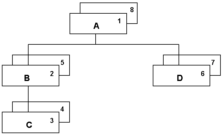
Each box represents a segment instance in the hierarchy. (Although
the diagram depicts two instances of each segment type, there may
be more or fewer instances of any type.) The numbers in the boxes
indicate the order in which IMS accesses the segments when an application
requests sequential access (for situations that allow sequential access).
This ordering of segments is called the hierarchical sequence.
A database record consists of a root segment instance along with
all of its descendant segment instances in hierarchical sequence.
The hierarchical path to a segment instance consists of the
segment itself and all of its ancestors starting from the root.
A segment consists of fields. A field is the smallest logical
unit of data that an application can request.
x
In IMS, the key field of a segment is called the sequence
field. It identifies the segment. A key is called unique if
no two segments can contain the same key value.
The value of the sequence field for a segment determines its
position in its chain of twins (segments of the same type under
the same parent). The primary key for an IMS database is the sequence
field of its root segment. This key identifies and orders the records
of the database.
In some IMS databases, the records are physically stored in root
key order. In others, the roots are stored randomly and retrieved
using a hash code (randomizing function) or an index.
Dependent segments are always retrieved by searching sequentially
from the parent to the first instance of the child segment type
and then through each occurrence of the child segment type, in order,
until the required instance is found. In some types of IMS databases,
dependent segments are physically stored in order of their sequence
field (if there is one). In others, the sequence is maintained by
pointers from one child to the next. However, even in this case,
the instances are initially loaded in sequence field order.
x
If you want to access a segment in order of a field
that is not its sequence field, IMS provides the option of creating
a secondary index on the field. In some situations, using a secondary
index improves performance. The secondary index is itself a separate database.
Each of its records contains a value of the field to be indexed
and a pointer to the target segment of the database record containing
that value.
When using a secondary index, IMS locates a record by first reading
the index database to retrieve the appropriate
pointer and then using the pointer to read the data database.
x
Another way to alter the order in which IMS views and
retrieves segments is through logical relations. A logical relation
associates segments from one or more databases as logical (virtual)
parents and children. The adapter cannot distinguish a logical database
from a physical database and can access both equally.
x
IMS database descriptions (DBDs) do not necessarily
describe every field in the database. They include entries for all
sequence fields, but other fields are optional.
When a DL/I retrieval request needs to locate specific database
records, it can include selection criteria on particular fields.
In some cases these search fields are not sequence fields.
In order to reference them in a DL/I call, the DBD must include
descriptions of these fields. See Describing a Database: The DBD in Overview of IMS Control Blocks for more information about IMS database descriptions.
x
When IMS traverses a database, it may follow pointers
from one segment to the next. In many cases the pointers are symbolic.
That is, they are key field values rather than actual addresses.
The symbolic pointer to a segment instance (also called its concatenated
key) is the concatenation of the key values of all segments
along the hierarchical path to that segment, starting from the root.
All access to dependent segments is through the root.
xOverview of IMS Access Methods
IMS supports several specialized access methods for
storing and retrieving segments of a database. These can be subdivided
into sequential and direct access methods. In the sequential methods,
IMS maintains the hierarchical sequence by physically placing the
segments in sequence. In the direct methods, IMS maintains the sequence
with pointers. The adapter supports any IMS access method that allows command
codes and qualified SSAs. The most common ones are:
-
HSAM (Hierarchical Sequential Access Method). The
database is stored physically in hierarchical sequence as on a tape.
Updates require rewriting the entire database. No direct access
is possible.
-
HISAM (Hierarchical Indexed Sequential Access Method). Initial loading
of the database is in physical sequence with the tail ends of records
that are too long going into an overflow area. All insertions after
initial load are in the overflow area. There is an index for direct
access to the root segment. The sequence field, or key, must be
unique. That is, no two root segments can contain the same key value.
-
HDAM (Hierarchical Direct Access Method). Root segments
are inserted by applying a randomizing routine to the sequence field.
The value computed assigns a storage location to the segment. Root
segments are retrieved by applying the same hash code. Descendant
segments are stored independently and linked by pointers. Since
the roots are stored in a random physical sequence without an index, they
cannot be accessed sequentially in root key order.
-
HIDAM (Hierarchical Indexed Direct Access Method). The
database consists of two parts, the data database
and a separate database that is an index on the sequence field of
the root segment. The data database is physically
loaded in hierarchical sequence. Roots can be accessed sequentially
or directly, but each direct access requires reading the index database
prior to reading the data database. Root
sequence fields must be unique. That is, no two root segment instances
can contain the same key value.
-
DEDB (Data Entry Database). This is a Fast Path access
method. Fast Path is an option that provides enhanced data
reliability and availability and improved response time in exchange
for limitations on the structure of a database and on its ability
to take advantage of techniques like secondary indexing and logical relationships.
DEDBs can have special segments called sequential dependents that segregate
high volume data and make loading the database more efficient. DEDBs
can also be subdivided into areas, each of which contains all segment
types for particular roots, thus partitioning the database by root
key values. (This differs from data set groups that are available
for many types of data sources and that segregate particular types
of segments for all roots.) The advantages include the ability
to create very high volume databases, to make most of the database
available even if an area is undergoing maintenance, and to replicate
areas for increased availability and problem recovery.
-
MSDB (Main Storage Database).
This is a Fast Path access method
that limits the database structure to root-only databases with no
logical relationships, secondary indexes, variable length data,
or field level sensitivity. The major advantage of MSDBs is the
extremely fast access that IMS achieves by loading and accessing
them in main storage in the online (IMS/DC) region. You can access
MSDBs only through the BMP mode of program DFSRRC00 (see Environments for information)
because they exist in the IMS/DC region.
xOverview of IMS Control Blocks
IMS uses special control blocks for describing a database,
regulating application access to databases, and communicating with
an application. This section briefly describes these control blocks.
x
Describing a Database: The DBD
The DBD (Data Base Description) is a control block that
describes the structure of a physical or logical database. It contains
information necessary for locating particular segments, specifies
access method and ddname allocation information, and describes the
hierarchical structure of the database.
To describe the structure of the database, the DBD contains SEGM
and FIELD statements:
- SEGM statements name the segments and their parents and
specify their lengths and pointer types.
- FIELD statements name the fields, specify their positions within
the segment, describe their data types, identify whether they are
sequence fields, and, if they are sequence fields, specify whether
they are unique or non-unique. FIELD statements are not required
for all fields in the database. They are required for sequence and
search fields.
If the database participates in a logical relation, the DBD may
include logical child information.
After the actual database description, the DBD includes a DBDGEN
statement that instructs IMS to take the user-provided DBD source
statements and create a load module that the system can use. Sample File Descriptions,
illustrates sample DBDs.
x
Defining Application Access to Databases: The PSB
The PSB (Program Specification Block) contains information
about authorization of an application to use databases. Each view
of a database that the application can access is described within
the PSB. This description is called a PCB (Program Communication
Block, described in Describing a Database View and Communicating With the DBMS: The PCB).
Therefore, the PSB is simply a collection of PCBs.
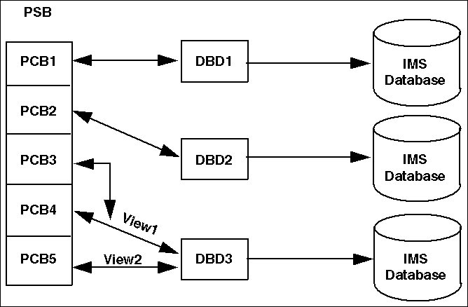
The PSB can contain two types of PCB. One type provides access
to databases (TYPE=DB) and the other type implements teleprocessing
communication and batch checkpointing (this type is called an I/O
PCB, TYPE=TP). The PSB can contain duplicate PCBs for maintaining
multiple positions within a database or for performing recursive
joins. The PSB can also include multiple PCBs for the same database
in order to provide different views of the database or to allow
different types of access to the database.
The PSB ends with a PSBGEN macro statement that contains information
about the PSB, such as its name. The PSBGEN creates a load module
from the source statements. Sample File Descriptions illustrates sample PSBs.
x
Describing a Database View and Communicating With the DBMS: The PCB
A PCB (Program Communication Block) has several functions:
- It describes a view of a database. That is, it names the
database to be accessed (the DBDNAME parameter), lists the segments
that a program can access through that PCB (the SENSEG statement),
and names the parent of each sensitive segment (the PARENT parameter).
- It describes the type of access to the database that a program
can have through that PCB (the PROCOPT parameter). For example,
it may limit requests to retrieval only.
- It may specify that a secondary index is to be used as the main
entry point into the database (the PROCSEQ parameter).
- It keeps track of position within the database. That is, it
remembers which segment was retrieved the last time the PCB was
used.
- It receives a status code from the DBMS about the results of
each call it makes to the database.
In a PSB, the PCBs are listed one after another prior to the
PSBGEN statement. I/O PCBs must come before database PCBs. A segment
cannot be included in a PCB unless its parent is also included.
For the root segment, PARENT=0.
An application program can use all PCBs in a PSB concurrently.
The program gives a name to each PCB and defines its structure by
applying a mask that allocates program variables to receive the
status information returned by IMS. Although IMS returns status information
to the PCB, it does not place the retrieved database segment into
the PCB. The segment goes into an I/O area identified in the DL/I
call (see Overview of DL/I Calls).
For PCB examples, refer to the PSB samples in Sample File Descriptions.
The following diagram illustrates the relationship between DBDs,
PSBs, and PCBs.
x
All access to segments within an IMS database proceeds
from the root segment through the hierarchical path to the desired
segment. When an application has no use for the data in a segment,
but does need data from one of its children, the PCB can specify
PROCOPT=K to make the parent segment key sensitive. This
gives IMS access to the key value of the segment but instructs it
not to return any data from the segment to the application.
x
A PCB can include an optional list of sensitive fields
for a segment (the SENFLD statement). If it does, IMS returns only
those fields to the application, not the entire segment. This field
level sensitivity provides data independence and security. Even if
the segment changes, the PCB and application program can remain
the same. Also, for security purposes, application programs can
only access specified fields.
x
IMS stores a status code in the PCB after each DL/I
call. The adapter checks the status code after each call to determine
whether the call was successful and if not, why not.
x
After a successful call, the key feedback area in
the PCB contains the concatenated key of the retrieved segment
(the keys of each segment in the hierarchical path to the retrieved segment).
x
An ACB is an optimized PSB that contains a combination
of information from the PSB and the DBD. However, even with an ACB,
the normal PSB is still required. ACBs are created by an ACBGEN
and are used to access online databases.
x
To access an IMS database, an application program must
call a special DL/I subroutine, such as ASMTDLI (Assembler to DL/I).
Each DL/I call passes IMS the following arguments:
- A function code that defines the type of call. The adapter
makes only two types of calls: GU (Get Unique) and GN (Get Next).
- The PCB to use for the call.
- The I/O area in which to put the retrieved segment.
- Segment search arguments (SSAs) that describe the desired segment.
The number of SSAs in a call depends on the level of the segment
to be retrieved and the type of call. The following section discusses
SSAs in more detail.
x
If you want to retrieve a specific segment or type of
segment, you must tell IMS how to find it. You do this by means
of segment search arguments (SSAs).
There are two types of SSAs:
- An unqualified SSA consists of a segment name. Any
segment of that segment type satisfies the SSA.
- A qualified SSA is a Boolean expression that defines
an acceptable value or range of values for one or more fields in
the segment. The fields referred to in the SSA must be search fields.
That is, they must be listed in FIELD statements in the DBD. Only
segments containing the proper values satisfy a qualified SSA.
SSAs can also include command codes that alter the way in which
IMS completes the call. For example, the FIRST command code (*F)
instructs IMS to begin its search at the start of the twin chain
for that segment type, under the current parent, even if the PCB
is positioned past that point. The adapter uses only one command
code, the *U (parentage) command code. Tracing Adapter Processing,
includes a trace example that demonstrates the use of this command code.
x
The adapter retrieves data from IMS using two types
of Get calls:
-
GU (Get Unique) always starts from the beginning
of the database and finds the first segment that satisfies all of
the SSAs. It uses the index or hash code to locate an appropriate
root segment. The segment type named in the last SSA is the type
of segment that IMS retrieves and places in the I/O area.
-
GN (Get Next) provides sequential retrieval. It keeps
track of which segment was last retrieved (the current database
position) and goes on from that point. It can be issued with
or without SSAs. If there are no SSAs, it retrieves the next segment
listed in the PCB in hierarchical sequence. This segment can be
any type of segment. If there are SSAs, it retrieves the next segment
that satisfies all of the SSAs. The last SSA determines the type
of segment that IMS retrieves and places in the I/O area. Since
HDAM roots cannot be retrieved in root key order, using GN calls
on HDAM roots retrieves them in the random physical order in which
they were loaded.
For a discussion of how the adapter creates SSAs, see Reporting Efficiencies.