In this section: |
Flows are built and modified in the DataMigrator workspace. Objects can be dragged into the workspace from the navigation pane and, when in process flow mode, from the process flow toolbar.
For data flows and process flows, the workspace consists of the following tabs:
Other tabs are available when creating different types of data flows:
Note: When building different types of data flows, a Process Flow and Text View tab are also available.
For synonyms, the workspace consists of the following tabs:
For details about synonyms, see Working With Synonyms.
How to: Reference: |
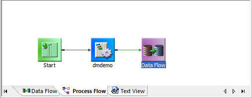
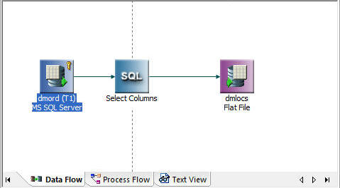
The Data Flow tab is where you build data flows to extract and move data from data source objects to data target objects. Arrows connect the objects and support the flow.
The following image is a sample of a simple data flow in the Data Flow tab.
The flow is checked for errors.
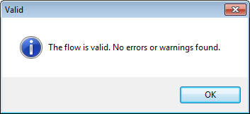
If errors are found, a warning message appears, as shown in the following image.
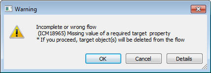
Data flow objects appear as follows in the workspace:
Object |
Function |
---|---|
|
Data source - sourcename (Tn) or appdir/sourcename (Tn) Indicates a data source for the data flow, where sourcename is the name of the synonym and Tn is the table number. A key icon in this object indicates that the synonym has a key identified. |
|
Inner Join Indicates that two data sources are connected by an inner join and that only rows that appear in both tables used in the Join are extracted. |
|
Left Outer Join Indicates that two data sources are connected by a left outer join and that all rows are extracted from the left data source, as well as the columns from the right source that match. |
|
Right Outer Join Indicates that two data sources are connected by a right outer join and that all rows are extracted from the right data source, as well as the columns from the left source that match. |
|
Full Outer Join Indicates that two data sources are connected by a full outer join and that all rows are extracted from both data sources. |
|
Cross Join Indicates that two data sources are connected by a cross join, or Cartesian product of two tables. It consists of all possible pairs of rows between the two tables. |
|
SQL/Select Columns Contains the generated SQL used to extract the data, based on selected columns, filters, and sorts used in the data flow. A filter, or sort, icon in this object indicates when a filter or sort has been specified. |
|
Union Indicates that two SQL objects are connected by a union intersect or minus. A different icon appears when Intersect or Minus is selected. A pages icon appears when ALL is selected. |
|
Target - targetname or appdir/targetname Indicates a target for the data flow, where targetname is the name of the synonym. A key icon indicates if the target table has key columns identified. A red star on the icon indicates a new target table. |
How to: |
DataMigrator features a number of calculators for creating transformations and filters using columns, variables, and functions. These columns, variables, and functions can be used in the Synonym Editor to create virtual columns.
These items can be displayed either in a tree or in a list. When displayed in a list, they can be sorted either ascending or descending. You can also search for items.
You can customize the information that is available for columns, as well as how they are displayed.
Note: Tree view is the default for the calculators and for the Synonym Editor. List view is the default for Join Properties and Column Selection (SQL object).
To open a calculator, click the Insert or Compute button, or select WHERE or HAVING Filter from the SQL Object context menu.
The Columns/Variables tab defaults to the tree view. To change it:
The columns and variables are now shown in a list, as shown in the following image.
To open a calculator, click the Insert or Edit button, or select the WHERE Filter from the SQL Object right-click menu.
Calculators open to the Columns/Variables tab using the default tree view.
To change the display of functions:
The functions are now shown in a list.
Double-clicking a synonym opens the Synonym Editor.
The columns are now shown in a list.
The information displayed for columns is controlled by the Column Management pane of the Options dialog box.
In a calculator or the Synonym Editor:
The Column Management pane of the Options dialog box opens, as shown in the following image.
The columns will now appear in the order you specify in calculators or the Synonym Editor.
Reference: |
The Process Flow tab is where you build process flows. Arrows connect the objects and support the flow.
The following image is a sample of a simple process flow in the Process Flow tab.
Process flow objects appear as follows in the workspace:
Object |
Function |
---|---|
|
Start Indicates the start of the process flow. Start is always the first object in the process flow. The Start object contains the scheduler attributes for the process flow. You can schedule a flow to run once, on a recurring basis, or on a specified days of the week or month, on an interval you define. |
|
Data Flow Indicates an embedded data flow that contains data source and data target objects, along with business rules that govern what is extracted and moved from source to target objects. To open the data flow, right-click the flow and select Open. Note: This icon appears when the data flow is embedded in a process flow. |
|
Flow Indicates that a complete data flow or another process flow is being executed from the current process flow. You can nest one flow within another. To open the flow, right-click the flow and select Open. Note: This icon appears when a previously saved data flow or process flow is executed from the current process flow. |
|
Parallel Group Indicates that a group of flows or procedures will be executed simultaneously. The group object is generally followed by a Wait object. |
|
Wait Indicates that processing of the next object in the flow will wait until execution of all processes in the parallel group have been completed. A Wait object generally follows a Parallel Group object, but is not required. |
|
Indicates an email message is sent at the designated points in the flow. email can be sent to multiple email addresses at any point in a process flow. Remember that the server must be configured for sending email. |
|
Stored Procedure Indicates a saved procedure (other than a data or process flow). The stored procedure can be any 4GL program that is executed during a process flow. |
|
Connector Represented as arrows, connector objects specify the logic that governs what is executed next in a process flow. In some cases, the logic is unconditional. In others, the logic is conditional (set either by defaults or by conditions you define). The color of the arrows indicates these relationships:
|
|
Set variables Set default values for variables used by other objects in the flow. |
The Text View tab allows you to view the underlying code for a flow.
Note: You can use CTRL + F or select Find from the Edit menu to search the text. After you close the Find dialog box, you can use F3 to find the next occurrence and Shift + F3 to search backwards.
iWay Software |