This section describes how to create Model Projects
using iWay MDS and manage them by defining a connected system, defining
the MDS logical model, and generating MDS resources (transformations
and batch interfaces).
x
Creating a New Model Project
A new Model Project consists of connected systems, the
MDS logical model, the database, transformations, batch interfaces,
and files.
x
Procedure: How to Create a New Model Project
To
create a new Model Project:
-
From the Model Explorer tab, click New
Model Project as shown in the following image.
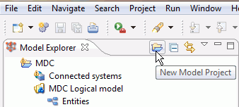
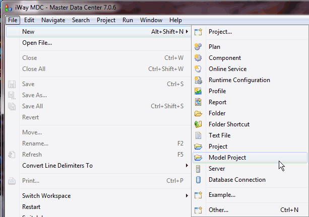
You can also create
a new Model Project from the File menu as shown in the following
image.
-
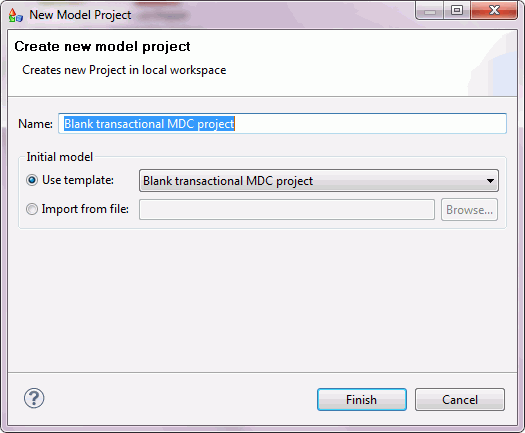
The New Model Project dialog appears, with a default
project name and associated template, as shown in the following
image.
-
Enter a unique name in the Name field
(for example, Buyer Supplier Contact MDS Project).
-
The following are the available options for the Initial
model area.
-
Use template. Select from one of the following predefined
templates:
-
Blank transactional MDS Project. Creates
a new project with structured files that do not contain any default
tables or files.
-
Transactional CDI project. Creates a new project with
structured files containing several default tables and files.
-
Bulk Profiling. Creates a new project to generate an
analysis of data sources containing multiple tables.
-
Import from file. Use this option to import a Model Project
from an existing file.
Select the Blank Transactional
MDS Project template.
-
Click Finish.
A new Model Project with supporting artifacts is created
as shown in the following image.
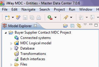
A Model Project consists
of the following components:
-
Connected Systems. Informs
iWay MDS where your input data is coming from and how it is defined.
Input interfaces can be Batch, Online, or both. Entities or precursors
to the MDS logical model, with an instance ID to relate entity tables,
must be defined.
-
MDS Logical Model. Consists of Instance and Representative (master)
layers. Relationships between the objects are also Instance and Representative.
The logical model contains loaded data, which is stored in an MDS repository.
-
Database. Generated when the MDS logical model is defined.
-
Transformations. Data quality plans for cleaning, matching,
and merging input records into the MDS logical model. Initially,
transformations are automatically generated, but each plan will
require additional logic to clean, standardize, match, and, merge
instances into the MDS repository.
-
Batch Interfaces. Contain Read and/or Write plans for
each connected system. Batch interfaces are automatically generated
initially and only contain the Integration Output for each entity.
Logic can be added to read input and modify output.
-
Files. A series of folders that consist of component
files used to execute batch and online data feeds into the MDS logical
model:
-
/batch. Consists of files generated for batch
interfaces.
-
/bin. Consists of batch processing Start and Stop applications
for the iWay MDS engine.
-
/data. Holds supporting files for transformation plans.
-
/etc. Contains XML files to execute online Web Services
or events.
-
/trans. Contains all the data quality plans used to load
the MDS logical model.
x
Defining a Connected System
A connected system is the structure of each source system
that is connected to iWay MDS for each Model Project. In the connected
system artifacts, define Batch Load plans including settings such
as Interface, Operating Mode, and size of the batch increments.
The connected system defines the entities of a logical model.
Entities should be related, where the Instance ID must be defined
to show how entities are related. Source ID must be defined as a
key to each entity.
Note: Source ID consists of the connected system name
plus the connected system table name, anchored by name of an entity.
The process of defining a connected system consists of:
- Adding a new connected system
- Defining a contact table
x
Procedure: How to Add a New Connected System
To
add a new connected system to a Model Project:
-
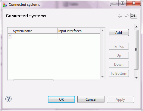
Double-click Connected Systems in the
Model Explorer tab, the Connected systems dialog opens, as shown
in the following image.
-
Provide a name to identify the new connected system by
double-clicking in the System name column and entering a value (for
example, Shipper).
-
Double click the empty row in the Input interfaces column,
and select a value from the drop-down list.
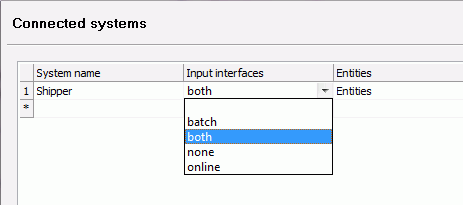
The available Input
interfaces are described as follows:
|
Input Interface
|
Description
|
|---|
|
batch
|
The connected system and its entities can only
accept input through batch interface loads.
|
|
both
|
The connected system and its entities accepts
input from both Batch and Online Interfaces.
|
|
none
|
The connected system does not
accept either Batch or Online inputs.
|
|
online
|
The connected system and its entities can only
accept input through an Online or Web Service load.
|
For the Buyer Shipper project, select both.
-
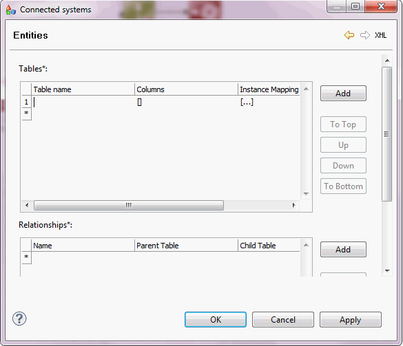
Double-click the empty row in the Entities column. Click edit element,
which appears automatically.
The Entities pane of the Connected systems dialog opens,
as shown in the following image:
-
Double-click the empty row in the Table name column and
enter Contact
-
Double-click the empty row in the Instance Mapping column
and click edit element, which appears automatically.
The Instance Mapping pane of the Connected systems dialog
opens, as shown in the following image:
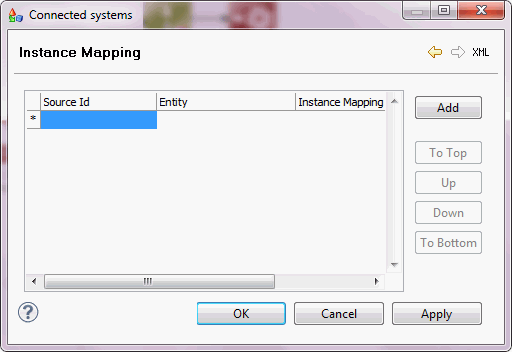
Enter the values in
the Instance Mapping pane, as listed in the following table:
|
Source ID
|
Entity
|
Instance Mapping
|
|---|
|
Shipper_Contact#BuyerShipper
|
BuyerShipper
|
instance_id
|
|
Shipper_Contact#ShipperDetails
|
ShipperDetails
|
instance_id
|
|
Shipper_Contact#Details
|
Details
|
instance_id
|
-
Click OK and Save the project.
x
Procedure: How to Define the Contact Table
To
complete a connected system, you must define a contact table. The
contact table provides the metadata of the incoming data source.
To
define a contact table for the sample connected system (Shipper):
-
Import the incoming data to configure metadata.
-
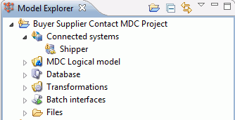
Expand the Connected systems node as shown in the following
image:
-
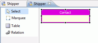
Double-click the Shipper connected
system. The Shipper tab opens in the workspace area, as shown in
the following image:
-
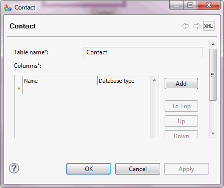
Double-click the empty Contact table which
is empty by default.
The Contact dialog opens as shown in the following image:
For demonstration
purposes, enter the values as listed in the following table:
|
Name
|
Database type
|
|---|
|
id
|
integer
|
|
type
|
varchar(10)
|
|
name
|
varchar(100)
|
|
gender
|
varchar(20)
|
|
contract_date
|
varchar(100)
|
|
fed_eid
|
varchar(20)
|
|
shipper_card
|
varchar(20)
|
|
mupdate
|
varchar(100)
|
-
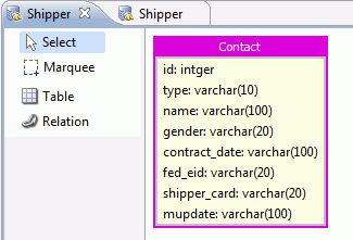
Click OK when complete. The contact
table should have a structure, as shown in the following image:
Now that a connected
system has been created with a defined contact table, the next step
is to define the MDS logical model.
x
Defining the iWay MDS Logical Model
The iWay MDS logical model is the architectural representation
of how you want to maintain the standardized set of records of your
enterprise data. The logical model is also a Data Repository for
storing the Cleaned, Matched and, Merged instances.
The MDS logical model can be a single logical table or a set
of related denormalized logical tables. The Master Data Repository
consists of Master Data, Instance, Definition Master Data and, Metadata
for the MDM system. It can hold history data that records changes
to the Master Data.
Metadata resides in the Master Data Repository and can be created
from scratch or imported to support the Configuration and Administration
of the MDM system for functionality such as Data Validation, Data
Cleansing, Deterministic Matching and Merging criteria from Business
and Data Governance rules.
You can create a Model from scratch or parts of it can be imported,
either by importing Database Metadata or as an XMI file. You can
also use other model builders and integrate with iWay MDS.
The steps to build a logical model consist of two processes,
defining the logical model Metadata and constructing a Relationship
Entity, as described below. You can choose to maintain records in
one table or multiple tables. In this example we will construct
multiple tables and relate them through a relation construct.
x
Procedure: How to Define an iWay MDS Logical Model
Denormalize
the Shipper Contact data into three tables (BuyerShipper, ShipperDetail,
and Detail).
-
In the Model Explorer,
expand the MDS Logical Model artifact and
double-click Entities to open the MDS Editor.
-
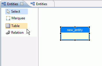
Click Table. Click anywhere in
the iWay MDS Editor to create an empty table entity as shown in
the following image.
-
Double click the new_entity artifact.
Enter BuyerShipper in the Table name field, as shown
in the following image.

-
In the Entity role field, select
from the following options:
For the BuyerShipper table, select entity.
-
The Matching mode field consists
of the following options:
For the BuyerShipper entity, select automatic.
-
In the Columns field, enter the
metadata information. In the Name field,
enter cmo_shipper_id for the BuyerShipper entity.
The options for the MDS type field,
are listed and described in the following table.
|
MDS type
|
Description
|
|---|
|
Boolean
|
True or False
|
|
date
|
yyyymmdd
|
|
datetime
|
yyyymmdd hh:mm:ss
|
|
float
|
|
|
integer
|
I2
|
|
long
|
I4
|
|
string
|
alphanumeric
|
-
For the BuyerShipper entity, select long from the
drop-down list, as shown in the following image.

The Column
role field can have one of the following choices.
|
Column role
|
Role Description
|
|---|
|
all
|
Original input field
|
|
instance
|
|
|
instanceid
|
Key field to the table can be
used in relationships
|
|
joined
|
Non-master join field
|
|
joinedMaster
|
Key field used to join tables
in a relationship
|
|
key
|
|
|
master
|
Master data field
|
|
masterId
|
Key master field in a table
|
|
output
|
|
|
source
|
|
|
standardized
|
Cleaned field
|
-
For the BuyerShipper entity, select masterId.
-
In the Database type field, enter integer.
-
Use the following table to complete the metadata for
the BuyerShipper entity.
|
Column name
|
MDS type
|
MDS role
|
Database type
|
|---|
|
instance_id
|
string
|
instanceid
|
varchar(20)
|
|
type
|
string
|
all
|
varchar(20)
|
|
name
|
string
|
all
|
varchar(100)
|
|
shipper_card
|
string
|
all
|
varchar(30)
|
|
fed_eid
|
string
|
all
|
varchar(20)
|
|
std_first_name
|
string
|
standardized
|
varchar(100)
|
|
std_middle_name
|
string
|
standardized
|
varchar(100)
|
|
std_last_name
|
string
|
standardized
|
varchar(100)
|
|
std_social_title
|
string
|
standardized
|
varchar(10)
|
|
std_aca_title
|
string
|
standardized
|
varchar(10)
|
|
cmo_first_name
|
string
|
master
|
varchar(100)
|
|
cmo_middle_name
|
string
|
master
|
varchar(100)
|
|
cmo_last_name
|
string
|
master
|
varchar(100)
|
|
cmo_social_title
|
string
|
master
|
varchar(10)
|
|
cmo_aca_title
|
string
|
master
|
varchar(10)
|
|
sco_name
|
integer
|
standardized
|
integer
|
|
sco_fed_eid
|
integer
|
standardized
|
integer
|
|
sco_shipper_card
|
integer
|
standardized
|
integer
|
|
sco_instance
|
integer
|
standardized
|
integer
|
-
Click OK and Save the project.
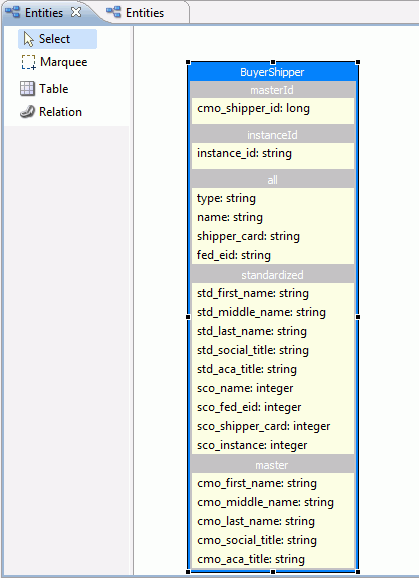
The BuyerShipper table entity should resemble the following
image.
-
Create two more tables utilizing the information below:
Table 1 - Details
-
Table name. Details
-
Entity role. entity
-
Matching mode. automatic
-
Columns
|
Column name
|
MDS type
|
MDS role
|
Database type
|
|---|
|
cmo_detail_id
|
long
|
masterId
|
integer
|
|
instance_id
|
string
|
instanceid
|
varchar(20)
|
|
fed_eid
|
string
|
all
|
varchar(20)
|
|
shipper_card
|
string
|
all
|
varchar(20)
|
|
contract_date
|
string
|
all
|
varchar(100)
|
|
std_fed_eid
|
string
|
standardized
|
varchar(20)
|
|
std_shipper_card
|
string
|
standardized
|
varchar(20)
|
|
std_contract_date
|
string
|
standardized
|
varchar(100)
|
|
cmo_fed_eid
|
string
|
master
|
varchar(20)
|
|
cmo_shipper_card
|
string
|
master
|
varchar(20)
|
|
cmo_contract_date
|
string
|
master
|
varchar(100)
|
|
sco_contract_date
|
integer
|
standardized
|
integer
|
Table 2 - ShipperDetail
-
Table name. ShipperDetail
-
Entity role. relationship
-
Matching mode. automatic
-
Columns
|
Column name
|
MDS type
|
MDS role
|
Database type
|
|---|
|
cmo_shipper_id
|
long
|
joinedMaster
|
integer
|
|
cmo_detail_id
|
long
|
joinedMaster
|
integer
|
|
instance_id
|
string
|
instanceId
|
varchar(20)
|
|
src_shipper_instance_id
|
string
|
source
|
varchar(20)
|
|
detail type
|
string
|
all
|
varchar(20)
|
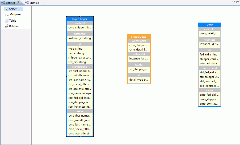
Once all the tables are constructed,
the iWay MDS logical model should resemble the following image.
x
Procedure: How to Construct a Relationship artifact
To
relate the three tables to one another, a relationship must be established
between them.
-
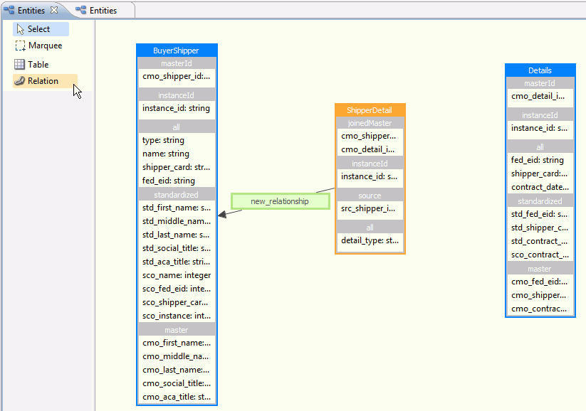
Click the Relation artifact.
Drag the pointer from the ShipperDetail table to the BuyerShipper
table and release the pointer, as shown in the following image.
-
Double click the New Relationship artifact
to edit.
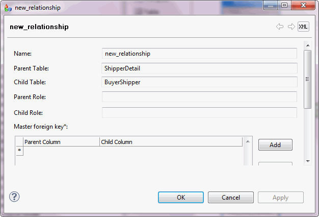
Enter the following new_relationship metadata
from the table below and click OK.
|
Property
|
Value
|
Description
|
|---|
|
new_relationship Name
|
shpdtl_buyer
|
unique meaningful name for the new_relationship
|
|
Parent Table
|
BuyerShipper
|
Automatically defined based on the direction
of the relationship
|
|
Child Table
|
ShipperDetail
|
Automatically defined based
on the direction of the relationship
|
|
Parent Role
|
buyer
|
|
|
Child Role
|
ShipperDetail
|
|
|
Master Foreign Key
| | |
|
Parent Column
|
cmo_shipper_id
|
From key field in the join
|
|
Child Column
|
cmo_shipper_id
|
To key field in the join
|
-
Save the project.
-
Click the Relation artifact to
create a relationship between the ShipperDetail table and the Details
table, as shown in the following image.
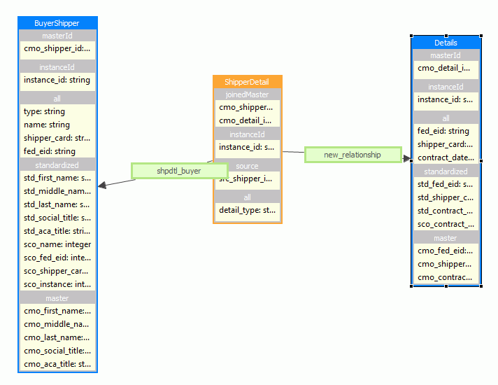
Double click the new-relationship
artifact. Enter the metadata from the table below and click OK.
|
Property
|
Value
|
Description
|
|---|
|
new_relationship Name
|
ShpdetDetr
|
Unique meaningful name for the new_relationship
|
|
Parent Table
|
Details
|
Automatically defined based on the direction
of the relationship
|
|
Child Table
|
ShipperDetail
|
Automatically defined based
on the direction of the relationship
|
|
Parent Role
|
Details
|
|
|
Child Role
|
ShipperDetail
|
|
|
Master Foreign Key
| | |
|
Parent Column
|
cmo_detail_id
|
From key field in the join
|
|
Child Column
|
cmo_detail_id
|
To key field in the join
|
-
Save the project.
x
Generating iWay MDS Resources
Aside from defining a data and relationship model, the
other primary task of iWay MDS is to define processes to Cleanse,
Match, and, Merge the data. Templates for transformation processes
can be automatically generated based on the tables in the logical model.
Once a table is defined, a database Instance and Representative
table are created. Instance Tables are used to define the attributes
to generate the Clean, Match and, Merge transformation plans and
represents all the input records. The Representative tables are used
to derive the attributes to generate the Master Data Record and
the MDS repository. For every table defined in the MDS logical model,
a table is created for each Instance and Representative artifact.
x
Procedure: How to Review Resources
Perform
the following steps to review what was generated when the tables
in the MDS logical model were created.
-
Expand the Database artifact.
Expand the Instance Tables artifact as shown
in the following image.
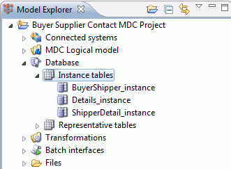
An Instance Table
is generated for each table created in the logical model. Double click
any Instance table to review.
-
Expand Representative tables
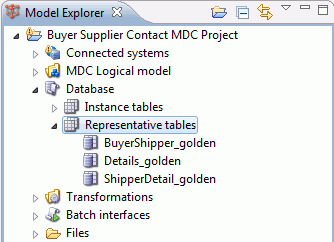
The different Golden
tables contain columns that represent the merged records that pass
through all the Data Quality transformation routines.
-
Expand the Transformations artifact.
For every defined table in the logical model, a Clean, Match and,
Merge plan is created. By default, three transformation files are
created for each table in the logical model. These files have the
suffixes _clean, _match, and _merge, since these three processes
are best designed separately as shown in the following image.
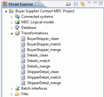
The plan contains
templates until a transformation is generated.
x
Procedure: How to Generate a Transformation
To
generate the transformation templates,
-
Right-click on the Transformations node
and select Generate, as shown in the following image.
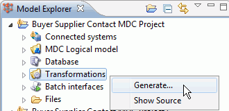
-
Specify the location for the generated files and click Generate.
-
Click OK.
This results in transformation files being generated for
each table in the logical model.
-
Double-click on any of the files to open the MDS Plan
Editor. The newly-generated files contain the following two algorithms
(steps) by default, shown below.
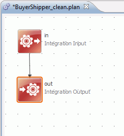
These steps are used
to receive incoming data and send data out, respectively, once it
has been transformed.
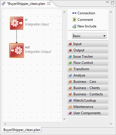
-
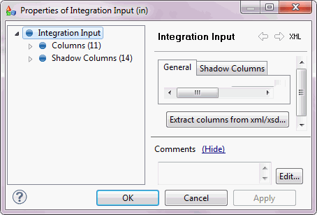
Double-click the Integration Input step.
The Properties pane opens as shown in the image below
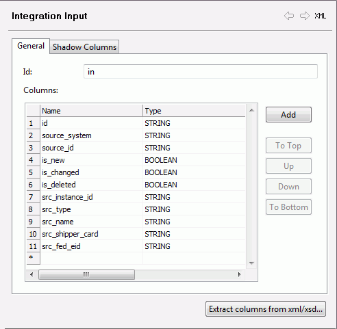
By default, the Input
step contains references to the columns from the table that was
used to generate the file, as well as some additional columns that
can be used to store data that are useful in the transformation
process, such as source_system and source_id,
as shown in the following image.
-
Click the Shadow Columns tab.
Shadow Columns are generated automatically and represent Cleaned
or Standardized columns that get passed to the Match plan.
-
Close the Integration input pane and the BuyerShipper_clean.plan.
The next step is to generate batch interfaces.
x
Procedure: How to Generate the Batch Interfaces
When
batch interfaces are generated, the Batch Load Data Quality Plan
is created. Three Integration Output steps are generated, one for
each table in the logical model. Additional input steps and logic
has to be added to send the input to the three Integration Output
steps.
When the plan is executed, at the end of each Integration
Output step, the Clean, Match and, Merge plans are executed for
each table. Data that is moved to each Integration Output is automatically
moved to the Clean plan first for each table.
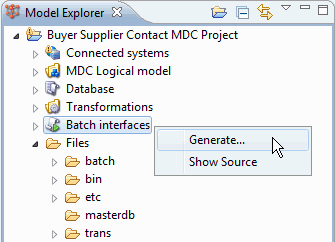
-
Right-click the Batch Interfaces artifact
and select Generate as shown in the image below.
-
Specify the location for the generated files and click Generate
-
Click OK.
-
Expand the Batch Interfaces artifact. Double click on
the plan file to open it.
The next step is to create the processes for Cleansing,
Matching or, Merging by adding intermediate steps and further configuring
the existing steps. This process varies depending on the quality
and format of the incoming data. Extensive help on each of the steps
is available from the Help Menu.


