Creating a Process Flow
|
In this section: |
|
How to: |
You must create a project before you can design a process flow. If you have not created a project, see Creating a Project for instructions.
Creating a process flow in iIT Designer is a drag-and-drop operation. Every process flow begins with a Start object, which appears in the workspace by default when you create a new process flow. A process flow must also contain at least one end object, which you can add to the workspace at any time. You cannot validate or publish a process flow without an end object.
To create a process flow, you will include one or more of the objects provided by iIT Designer. After you add an object to the process flow, you then establish a relationship between that object, and the previous object in the flow. This relationship defines how, and under what conditions, you can route the document through the process flow.
Procedure: How to Create a Process Flow
There are two methods to create a new Process Flow:
- On the main
menu bar, click File, then New.
Select Other... from the drop-down list,
as shown in the following image.
- In the Select
a wizard pane, expand the iWay Integration folder, select Process
Flow, and click Next.
- You may
also create a new Process Flow by right-clicking on the Flows folder
of the desired project. Click New and Process
Flow, as shown in the following image.
- The General
Properties dialog box is displayed, as shown in the following image.
- In the Project Folder field, use the Browse button to select a folder to contain the new Process Flow.
- In the Name field, type a descriptive name for the process flow.
- In the Description field, optionally enter a description for the new Process Flow.
- Using the Target Server Version drop-down list, optionally select a non-default target version, .
- Select the Enable taps check box to enable real-time data capture and reporting. For more information on configuring and using Taps, see the iWay Enable User's Guide .
- Click Finish.
The new Process Flow is listed in the Integration Explorer view
in the selected location. The workspace displays a Start object,
and the Properties pane appears below, displaying the properties
of the Start object.
You are ready to add objects to the process flow.
Adding Objects to a Process Flow
Once you have created a process flow, you can continue to modify its design by adding objects according to your requirements. Every process flow requires at least one End object to terminate the flow. This section describes how to include an object in your process flow. For details about each object available to you in iIT Designer, see Defining Process Flow Objects .
Procedure: How to Add an Object to the Process Flow
To add an object to the process flow:
- From the
Object toolbar, click the object icon you want to add, and either
drag it to the workspace, or click a blank area of the workspace.
Note: You can also right-click a blank area of the workspace. Select the object you wish to add from the New Process Flow Object dialog box.
The New (type) Object dialog box for the selected object opens. The following image shows an example of this dialog box for a new File object.
See Defining Process Flow Objects for details on defining the objects that are available in Designer.
- In the Name field, type a name for the object, or accept the default.
- In the Description field,
type a brief description of the object, or accept the default.
Depending on the object you are adding, this dialog box also includes the following option.
- Tap. Select the Tap check box to enable real-time data capture and reporting. The Tap option is selected by default if you enabled Taps while creating a new process flow. For more information on configuring and using Taps, see the iWay Enable User's Guide.
- Click Next.
Depending on the object you choose, there are one or more dialog boxes that present the parameter options for the object.
- When you are finished defining the object, click Finish.
The new object appears in the workspace. You can drag it to any position in the workspace.
Building Relationships Between Objects
The relationship between two or more objects in a process flow is represented by a color-coded line with an arrow that directs the flow of the XML input document. You define the relationships between objects as you build your process flow. If necessary, you can change the line properties, just as you can the object properties, of an existing process flow.
This section explains how to create a relationship between objects and how to edit existing relationships.
Procedure: How to Build a Relationship Between Objects
To build a relationship between objects:
- Select the object from where the document originates, and then hold the Ctrl key to select the object that will receive the document.
- Right-click
the object that will receive the document, and select Create
Relation from the menu options.
The Relation Configuration dialog box opens. The following image is an example of this dialog box with an OnCompletion Event.
- Select the
event for the selected objects from the Event drop-down
list.
The default (stock) events that appear depend on the objects you are working with. For instance, the first relationship you build between a Start object and another object allows only the OnCompletion event for that relationship. The lines in the workspace that represent the relationship between two objects are color coded for quick identification. The following list describes the available events and the corresponding color.
- OnCompletion. Represented by a blue line. Indicates there are no conditions; always follow the path.
- OnError. Represented by a red line. Follow the path if there is a JAVA exception.
- OnSuccess. Represented by a green line. Follow the path if there is normal completion.
- OnCustom. Represented by a brown line. Allows you to customize the path condition.
- OnFailure. Represented by a maroon line. Follow the path if a coded error occurs, for example, an agent that is coded to issue an error when it is unable to connect to a server.
If you select OnCustom, a list of Case of options appears, allowing you to customize the event for a particular condition, such as true or false. The following image shows this dialog box for the line configuration between a Decision Switch object and an End object, and contains an Event drop-down list, and a table with three columns: Case, Type, and Description.
Note: The cases listed in the Case column are based on the agent. For example, the cases listed for HTTP and SQL are different.
- To add additional OnCustom cases, click the green plus sign (+) on the right of the Relation Properties dialog box.
The New Custom Event dialog box opens, as shown in the following image.
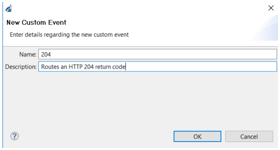
- Type the expected return code and description, based on the protocol of the agent.
- Click OK.
The Object Relation: OnCustom dialog box opens, as shown in the following image.
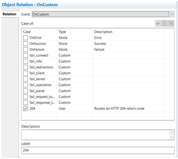
- Select 204 from the Case list.
You can use the Label field to show a label on the relationship line, as shown in the following image. The relationship line will now route only a 204 return code.
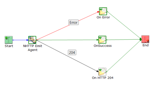
Note: The emit agent returns two edges at the same time, the specific HTTP status code followed by a more generic edge like you see in the Object Relation: OnCustom dialog box. For example, 404 and then fail_client. Since 404 appears first, if you wire it, it will be followed in preference to fail_client. In this case, you would get 204 and then success. If you wire 204, it will be followed in preference to success, which is shown as OnSuccess in the GUI.
- Click Finish.
A line appears between the two objects to indicate a relationship is established.
Procedure: How to Edit the Relationship Between Objects
If you want to change the properties of an existing relationship:
- Click the line that represents the relationship you want to edit.
- The relation
properties are displayed in the Properties tab, in the bottom portion
of the console.
The Properties pane provides an Event drop-down list, along with Case of and Description fields.
- Change the property as needed. (The properties of the relationship object change simultaneously.)
The new line properties are now in place.
Saving a Process Flow
To save a process flow, highlight the process flow node, and select Save from the File menu.