Introducing iIT Designer

In this section:

About Designer

The capability of graphically visualizing a business process is a powerful and necessary component of any application integration offering iIT Designer, a Windows based design-time tool that provides a visual and user-friendly method of creating a business process, also called a process flow.

Through a process flow, you control the sequence in which tasks are performed and the destination of the output from each task in the process flow. In the Designer user interface, you can create a project that holds one or more process flows. Each process flow you create is a single unit of work made up of one or more process objects, such as an Email, Adapter, or Emitter, which are graphically represented by icons and connected by lines that establish a relationship between the objects.

iIT Designer provides a unified iWay toolset for designing and integrating process flows. Through Designer, you can perform the following functions:

iIT Designer also offers concurrency control by checking process flows in and out of a repository. This prevents people from simultaneously working on a process flow.

When the design of a process flow is complete, you can use the validation option to confirm that the objects and their relationships meet the design criteria. You can also test the process flow by executing it with an actual input document to see results. When you are satisfied that the process flow is stable, you can publish it, making it available to iWay Service Manager. For details on compiling, validating, testing, and publishing a process flow, see Managing Process Flows
Understanding the Process System

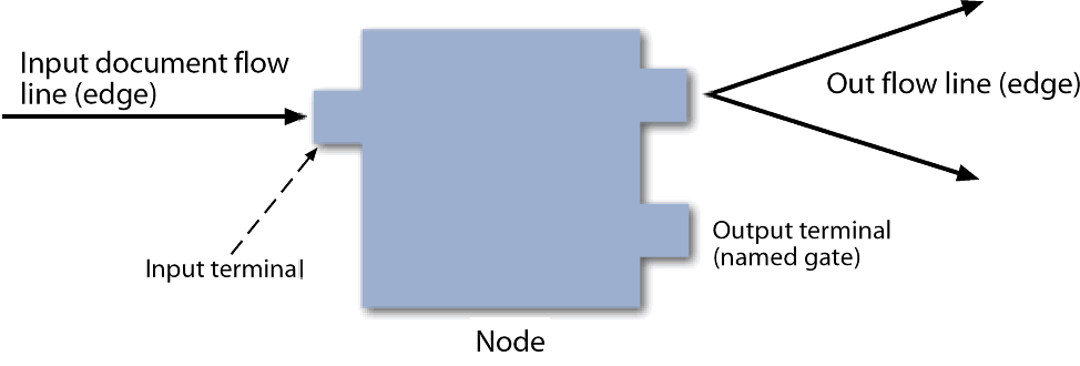
A process system links together a logical set of component objects into an iWay process flow to create an application. These nodes are interconnected in an application by edges along which documents flow. An edge segment stretches from the output terminal of one node, to the input terminal of the next node. The following image shows a single process flow node with an input terminal, into which input documents enter the node, and two output terminals, from which the documents leave the node. The processing within the node determines from which terminal the document leaves the node.

Application flows are published to iWay Service Manager at run time and are stored in the iWay configuration repository.

Integration Projects

An Integration project is the top level organization of resources from which you build process flows in iWay Integration Tools. Integration Projects are used for version management and the sharing and organization of resources. Project resources include process flows, services, transforms, adapters, emitters, and schemas.

Projects can be associated with either a named run-time server configuration or a Registry. Your choice of project association should be determined by where you intend to publish (deploy) your process flow. During the publishing process, all available targets are displayed. It is preferable to have your development environment be the same as your run-time environment.

For manipulating projects and developing processes from Designer, the iWay Registry functions much like a configuration. Unlike a configuration, the Registry is a design-time data store and it supports Service Manager’s channel architecture. If you are developing a process for use as part of a channel, you must publish it to the Registry for subsequent deployment. For more information about deploying channels, see the iWay Service Manager User’s Guide, Version 7 SM.

Integration Projects can contain a single process flow or multiple process flows. Process flows are designed within and for a specific project. Therefore, the project must exist before you create a process flow.

Process Flows

An Integration project holds the building blocks for the process flows that you will create under that project. These include services, transforms, adapters, emitters, and schemas.

iIT Designer also provides process flow objects, the executables within a process flow that direct and act upon the input to the process flow. The process flow is graphically represented in the workspace as a box and line diagram. The boxes are the objects you add, and the lines are the relationships you define between those objects. Designer includes executable objects. For example, a transform object converts a document from one format to another. Other objects control the flow of a document. For example, a Decision Test object routes a document based on a true or false condition. As you build a process flow, you will configure each object and the relationships between them to meet your requirements.

Once the process flow is created and saved, you can validate the structure and then test the process flow in a run-time environment. You can then make it available for use by publishing it to a run-time environment.


iWay Software