The iIT Designer Environment

In this section:

Explains how to navigate in iWay Designer and describes the options and panes available in the interface.

Starting Designer within iWay Integration Tools

To start Designer, double click the iit.exe file.

The workspace wizard pane appears as shown in the image below.
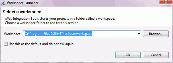
Click the Browse button to select a path for your Workspace, or accept the default path. Click OK.

The main iWay Integration Tools window opens, as shown in the following image.
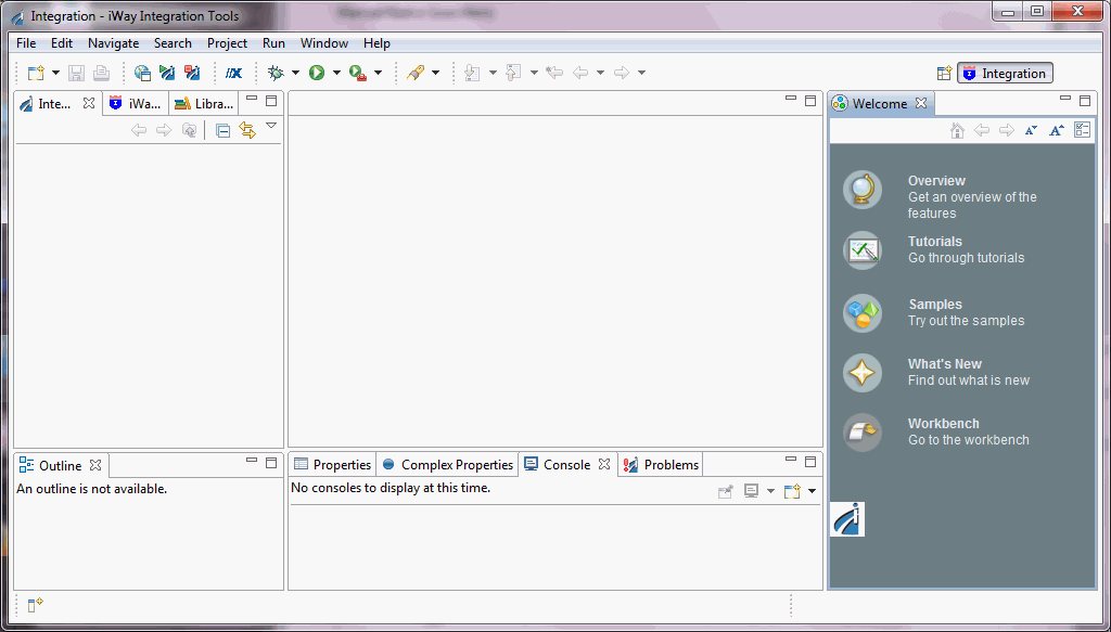
To utilize the functionality of iIT Designer, you must first create an Integration Project. See Creating a Project for more information. Once the Project is created, a new process flow must be created, as described in Managing Process Flows.

When a new process flow is created, the IIT Designer window provides access to all of the tools you will need to build the process flow. A set of menus and toolbars appear to the right of the window. Beneath them are the Layout and Properties panes. The following sections provide details on the display panes, the menu options, and the toolbar selections.

Once you open a Project and click on a Process Flow, most menu options and toolbar icons become available. Some menu options are only available when certain components of iIT Designer are selected.
Navigating the User Interface

In this section:

The Graphical User Interface (GUI) of iWay Integration Tools offers a variety of tools and options to assist you in creating projects and process flows. You can customize the GUI to fit your work needs. For example, you can drag toolbars and move, resize, minimize, or hide panes.

Like most applications, Designer provides several ways to perform a task and achieve the same result. Most tasks can be initiated from either a main menu option, a toolbar icon, or by right-clicking an item and selecting an option from the drop-down list. For example, to save a project you can do any one of the following:

The Designer Window

The Designer window provides the panes, illustrated in the following image, to construct your projects and display project-related information:

  1. The Navigator pane appears on the left. It contains the following tabs: Integration Explorer, Library Manager, and iWay Explorer. This pane provides access to the Designer repositories that contain your projects and process flows, the servers to which you can connect, iWay Explorer, and the available web services.
  2. The Workspace pane appears to the right of the Navigator pane. This is the area in which you build a process flow. The Workspace area contains two tab views, Design and Test Results. The Design view displays the Process Flow as you build it. The Test Results view displays test results of the last test run of a process.
  3. The Palette pane appears to the right of the Workspace area when a new Process Flow is created. The Palette pane contains all of the Objects and Relationship elements required to construct a Process Flow.
  4. The Layout pane appears below the Navigator pane. It displays a preview of the process flow as you create it.
  5. The Properties Window pane appears at the bottom of the workspace. This pane displays the attributes of the selected object in a process. You can change any attribute of the selected object from the Properties Window.

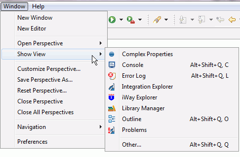
Any pane can be closed or accessed by clicking Window in the toolbar and selecting Show View, as shown in the following image.

Toolbar Icons

In this section:

When you start iIT Designer for the first time, a toolbar appears just above the Navigator Pane and the Palette appears to the right of the Workspace. The Palette contains the following sections:

Although the toolbar appears as a single unit, each category is contained between horizontal bars. You can drag the vertical bar to place a toolbar category on a separate line, or space it from the other toolbars within the toolbar area of the window.

Process Flow Toolbar

The Process Flow toolbar contains functions that apply to a Process Flow as a whole. Some functions are not available unless certain project components are selected in iIT Designer.

The icons that make up the Process Flow toolbar are shown below.

The following table describes each icon found on the Standard toolbar.

Icon

Description

Compile a process flow.

Open the Publishing Process tool.

Launch Property Manager

Undo or Redo the last action performed.

Align left, center, or right.

Align top, middle, or bottom.

Percentage magnification of Workspace area objects

The Palette Toolbar

In this section:

The Palette toolbar provides the fundamental options for working with objects in a process flow.

Palette Toolbar Selection

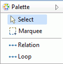
The icons that make up the selection area of the Palette toolbar are shown below.

The following table lists and describes the icons found on the selection area of the Palette toolbar.

Icon

Description

The Select option allows you to click to select a particular object or relationship.

The Marquee tool allows you to select an area in the workspace. Click inside the workspace and drag to select the area you want to work in.

The Relation is used to draw a line that represents the relationship between two objects in a process flow.

The Loop option is a special type of Relation (also called a line or edge) that works in conjunction with an Iterator object to repeat certain portions of a process flow over selected portions of one input document.

Basic Objects Toolbar

The Basic Objects toolbar provides fundamental options for working with objects in a process flow. The icons that make up the Basic objects toolbar are shown below.

The following table lists and describes the icons found on the Basic Objects toolbar. See Defining Process Flow Objects for a detailed description of each object.

Icon

Description

An End object terminates a process flow. At least one End object is required to terminate a process flow.

Text allows you to include text in the process flow. For example, you can label the relationship line that appears between objects.

Control Objects Toolbar

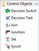
The Control Objects toolbar provides fundamental options for working with objects in a process flow. The following image shows the icons that make up the Control Objects toolbar. See Defining Process Flow Objects for a detailed description of each object.

Icon

Description

A Decision Switch object evaluates the contents of a document and routes it to the next object(s) based on the values in the document.

A Decision Test object evaluates the contents of a document and routes it to the next object(s) based on a true or false result.

A Join object combines two or more documents into a single document.

A Junction object combines two or more paths of execution into a single path.

A Set object initiates one or more process events that Synch objects are waiting on.

A Synch object waits for a condition to be met, such as the expiration of a time limit or the evaluation of an expression as 'true'.

Execution Objects Toolbar

The Execution Objects toolbar is shown in the following image.

The following table provides a brief description of the Execution objects. See Defining Process Flow Objects for a detailed description of each object.

Icon

Description

A BI object allows the process flow to execute a WebFOCUS report.

An Email object allows a process flow to send or receive an Email with one or more attachments.

An Emitter object adds an address to the payload using one of the supported protocols.

An ETL object executes a DataMigrator flow.

A File Object allows a process flow to perform file operations at execution time, such as read and write.

An FTP object allows the process flow to send or receive data using FTP.

An HTTP object allows a process flow to send or receive data using HTTP.

An Iterator object is a service object that is used in conjunction with a Loop object to process repeating sections of an input document.

A Process Lookup object inserts a published process flow into the current process flow as an object.

A Queue object sends or receives documents using a supported queue type.

A ReportCaster object allows a process flow to trigger one or more ReportCaster schedules, which then execute and distribute WebFOCUS reports or the contents of a URL or file.

A Script object allows you to execute JavaScript on an object in a process flow.

A Service object is a unit of work that emits default events and/or one or more custom events.

An SQL object executes an SQL request to a JDBC data source.

A Data Integration object iterates over an SQL result set and batch inserts.

A Transform object applies a selected transform to the document it receives in the process flow.

A Web Service object executes a web service.


iWay Software