Sample Configuration for Inbound Processing: EDI to XML

In this section:

This topic provides step-by-step instructions on how to configure a basic inbound message flow for the iWay Integration Solution for EDI. The message flow represents the movement and tasks in the conversion of a message from Electronic Data Interchange (EDI) format to XML format and acknowledgement of the message.


Top of page

x
Accessing the iWay Service Manager Administration Console

To access the iWay Service Manager Administration Console, you must first make sure that the iWay Service Manager service is running.

For instructions on starting iWay Service Manager, see the iWay Service Manager User's Guide.


x
Procedure: How to Access the iWay Service Manager Administration Console on Windows
  1. From the Windows desktop, select Start, All Programs, iWay 6.1 Service Manager, and Console,

    or,

    from a browser such as Microsoft Internet Explorer, enter the following URL,

    http://host:port

    where:

    host
    Is the host machine on which iWay Service Manager is installed. The default value is localhost.
    port
    Is the port number on which iWay Service Manager is listening. The default value is 9999.

    The following image shows the URL with the default values.

  2. When prompted, enter your user name and password, and click OK.

    Note: The default user name and password is iway.

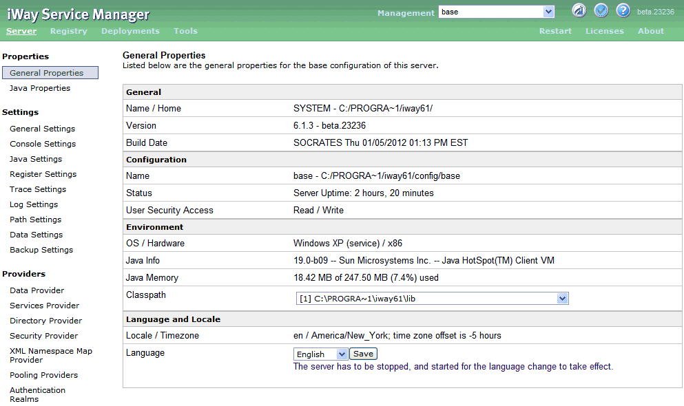
    The iWay Service Manager Administration Console opens, as shown in the following image.


Top of page

x
Adding an Ebix to the Registry

The iWay e-Business Information Exchange (Ebix) framework supplies several Ebix files for the iWay Integration Solution for EDI.

An Ebix file for EDI-X12 is named X12_transaction_set.ebx, where transaction_set is the transaction set number. For example, the Ebix file for EDI X-12 transaction set 4050 is named X12_4050.ebx.

For details on the supported EDI-X12 transaction sets, see Ebix-Supported Transaction Sets.

This topic describes how to add an Ebix to the Registry on Windows and UNIX.


x
Procedure: How to Add an Ebix to the Registry on Windows
  1. To access the Registry, select the Registry option in the blue shaded area below the iWay Service Manager banner, as shown in the following image.

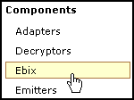
  2. Under Components in the left pane of the Registry, select Ebix.

    The Ebix pane opens, as shown in the following image.

  3. Click Add to add a new Ebix. The New Ebix pane opens.

  4. Browse to the directory in which the Ebix is located and select the name of the file, for example, X12_4050_pipeline.ebx.
  5. Once you have selected the Ebix, click Next.

    You are prompted for the name of the Ebix and an optional description.

  6. Enter a name for the Ebix, for example, EDI_4050, and an optional description, such as EDI 4050 Ebix.

    Note: This step must be repeated for each Ebix X12 message set that is added to the Registry.

  7. Click Finish.

    On the Ebix pane, you will see that the Ebix was successfully added. Later you will associate it with the channel for inbound processing.


x
Procedure: How to Add an Ebix to the Registry on UNIX

Depending on your system configuration, there are two methods that you can use to add an Ebix to the Registry on UNIX.


Top of page

x
Adding Special Register Sets

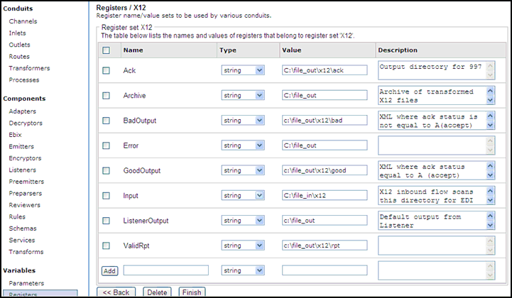
In iWay Service Manager, a special register is a name-value pair that defines a variable that is carried throughout the system. Once defined, this variable is available to all components of the system. Within the EDI components, a Best Practice is to use special registers to define inputs and outputs. When packages containing channels are migrated between systems, the only changes required to deploy in the new location is to modify these special registers and build the channel. Channels may have many locations and this practice will minimize the effort required to migrate. For a complete list of system special registers that are provided, see the iWay Service Manager Programmer's Guide. For more information on defining a special register of your own, see the iWay Service Manager User's Guide.

The sample inbound channel uses a set of special registers defined as X12. For example:


x
Procedure: How to Add a Special Register Set to Your Channel

To add a special register set to your channel:

  1. In the left console pane of the Registry menu, select Channels.

    The Channels pane opens.

  2. In the row for your channel, click Regs for the channel you want to modify.

    The Assign register pane opens.

  3. Select a register and click Finish.
  4. Click Back to return to the Channels pane.

Top of page

x
Defining an Inlet

An inlet defines how a message enters a channel. It typically contains a:


x
Procedure: How to Add a Listener
  1. From the Registry menu options on the left pane, select Listeners under Components.
  2. On the Listeners pane on the right, click Add to add a new listener.
  3. For the purpose of this example, we will show the configuration with a File listener. For details on supported protocols, see the iWay Service Manager Protocol Guide.

    Select File from the Type drop-down list and click Next.

    The configuration parameters pane opens.

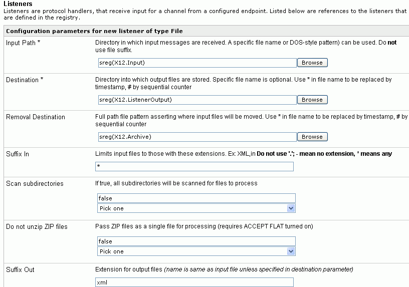
  4. Supply configuration parameters for the new File listener as follows. An asterisk indicates that a parameter is required. For parameters not listed in the following table, accept the default value.

    Parameter

    Value

    Input Path *

    sreg(X12.Input)

    This value is a special register that uses a defined directory in which input messages are received.

    Make sure that you have created this directory; otherwise, errors will occur during deployment.

    Destination *

    sreg(X12.ListenerOutput)

    This value is a special register that uses a defined directory in which output files are stored after transformation.

    Make sure that you have created this directory; otherwise, errors will occur during deployment.

    Removal Destination

    sreg(X12.Archive)

    This value is a special register that uses a defined directory to which input messages are moved if they fail during transformation.

    Make sure that you have created this directory; otherwise, errors will occur during deployment. It is recommended to configure a removal destination when you are constructing a basic channel.

    Suffix In

    *

    Input files with any file extension are allowed.

    Suffix Out

    xml

    The extension for output files is .xml.

  5. Click Next.

    You are prompted for the name of the listener and an optional description.

  6. On the Listeners pane, enter the name of the new listener, EDItoXML_Listener, and an optional description. Then click Finish to add the listener. In a later step, you will associate this listener with the inlet.


x
Procedure: How to Add a Preparser
  1. From the Registry menu options, select Preparsers under Components.
  2. On the Preparsers pane, click Add to add a new preparser. You are prompted for the type of preparser.

  3. Select EDIX12SplitterPreParser (com.ibi.preparsers.EDISplitPP) from the Type drop-down list.

    The EDIX12SplitterPreParser parses an EDI input file with one or more ISAs and multiple transaction sets (STs), and creates multiple XML output files. One XML output file is produced for each transaction set. You can also use the EDIX12SplitterPreParser if there is only one transaction set in an ISA.

    For details on the supported EDI-X12 transaction sets, see Ebix-Supported Transaction Sets.

  4. Click Next.

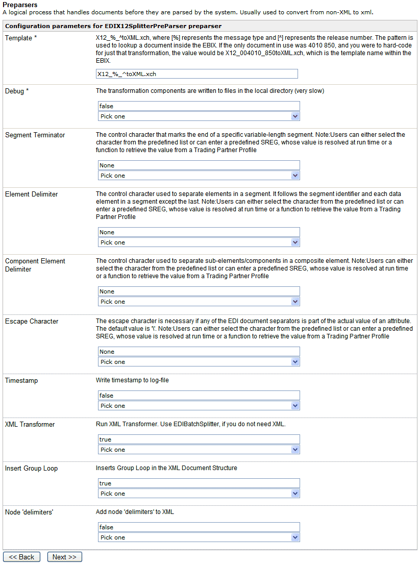
    The Preparsers configuration parameters pane opens.

    The following table lists and describes the available configuration parameters for the preparser:

    Parameter

    Description

    Template

    Used to locate the template in the Ebix used in the transformation from EDI format to XML format.

    Debug

    If enabled, the transformation components are written to files in the local directory. This parameter is set to False by default.

    Segment Terminator

    The control character that marks the end of a specific variable-length segment.

    To view a list of segment terminator characters, see Separators and Terminators.

    Element Delimiter

    The control character used to separate elements in a segment. It follows the segment identifier and each data element in a segment except the last.

    To view a list of element delimiter characters, see Separators and Terminators.

    Component Element Delimiter

    The control character used to separate sub-elements/components in a composite element.

    To view a list of component element delimiter characters, see Separators and Terminators.

    Escape Character

    The escape character is necessary if any of the EDI document separators is part of the actual value of an attribute.

    Timestamp

    Disabled by default, this option writes a timestamp to the log file. When enabled, the log file will display the start and end time of the file transformation and the input file name that is used. This feature is useful in development or debugging environments when processing batches of files. When the transaction log is not in use (for example, in a production mode) then this information is available in the Activity Log.

    Note: To use this feature, logging must be enabled in the Log Settings section of the iWay Service Manager Administration Console.

    XML Transformer

    Enabled by default, this parameter sets the EDIX12SplitterPreParser to transform the individual documents that are split from the incoming message into XML format.

    Note: Use the standalone EDI batch splitter preparser (com.ibi.preparsers.XDEDIBatchSplitter) if you do not require an XML transformation to be called.

    Insert Group Loop

    Inserts a group loop tag in the XML document. Group loop tags are displayed in activity logs and validation processing reports.

    Note: Ensure that this parameter is set to false. By default, this parameter is set to true.

    Node 'delimiters'

    If set to true, node delimiters are added to thegenerated XML document. By default, this parameter is set to false.

  5. In the Template field, enter X12_%_^toXML.xch. The preparser obtains the message type and version information from the EDI input document. In the parameter, the character "%" represents the message type, and the character "^" represents the version.

    For example, if the message type of the EDI input document is 810, and the version is 004050, the constructed template name is X12_810_004050toXML.xch.

  6. Click Next.

    You are prompted for a name and optional description for the new preparser.

  7. Enter a name for the new preparser, for example, EDItoXML_SplitterPreparser, and an optional description.
  8. Click Finish to add the preparser. In the next procedure, you will associate this preparser with an inlet.


x
Procedure: How to Define an Inlet

Now that you have added a File listener and splitter preparser to the Registry, you are ready to add and define an inlet. You will associate the previously created listener and preparser with the inlet.

  1. From the Registry menu options, select Inlets under Conduits.
  2. On the Inlet Definitions pane, click Add to add an inlet.
  3. On the New Inlet Definition pane, enter the name of the new inlet and an optional description, as shown in the following table. Then click Finish to add the inlet.

    Parameter

    Value

    Name *

    EDItoXML_Inlet

    Description

    Inlet for EDI to XML

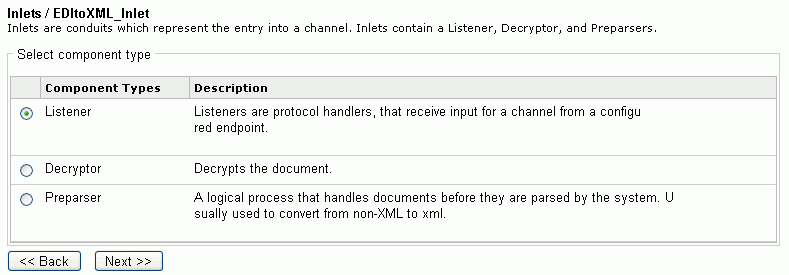
  4. On the Construct Inlet pane, click Add to associate the listener and preparser with the inlet.

    The next pane prompts you for the component type.

  5. Select Listener and click Next.

    The next pane prompts you to select a listener.

  6. Select EDItoXML_Listener, which is the listener you added earlier, and click Finish.

    The listener is associated with the inlet. Now you need to associate the preparser created earlier with the inlet.

  7. On the Construct Inlet pane, click Add.

    The next pane prompts you for the component type.

  8. Select Preparser and click Next.

    On the next pane, you are prompted to select a preparser.

  9. Select EDItoXML_SplitterPreparser, which is the preparser you added earlier, and click Finish.

    You have now successfully completed definition of the inlet.


x
Defining a Route

For this sample channel configuration, you will define a route that will invoke the X12 to XML validation process flow. The outcome of the validation process flow will place valid transformed XML data in a defined output folder. Invalid transformed data will be routed to an errors folder. An X12 functional acknowledgement and a validation report will be sent to their designated output folder defined in the sample channel.

This section describes how to create a validation process flow using iWay Designer and bind it to a sample inbound channel as a route.


x
Procedure: How to Create a New Project and Start the Process Flow

To create a new project and start the process flow using iWay Designer:

  1. From the Windows Start menu select Programs, iWay 6.1 Service Manager, tools, and then iWay Designer.
  2. Connect to the repository from which you want to work, for example, iWay.
  3. Right-click the iWay node and select New Project from the drop-down list.

    The Designer Project Information dialog box opens, prompting you for a project name and optional description.

  4. In the Name field, type a project name, for example, Test.

    In the Description field, type a brief description (optional) to describe the project and click Next.

    The Designer Project Bindings dialog box opens.

  5. To create the project in the iWay Registry, select iWay Registry and click Finish. The choice of project association depends on where you intend to publish (deploy) your process flow. If you are developing a process flow for use as part of a channel, you must publish it to the iWay Registry for subsequent deployment.
  6. The Test project node appears under the repository in which it was created (in this example, it appears under iWay).
  7. To save the project to the repository, right-click the project node and select Save from the context menu.
  8. Expand the Test project node to expose the project elements (such as Processes, Services, and Transforms).
  9. Right-click the Processes folder and select New Process from the drop-down list.

    The iWay Process Configuration dialog box opens.

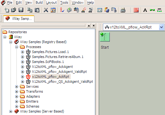
  10. In the Name field, type x12toXML_pflow_AckRpt as the process flow name.

    In the Description field, type a brief description (optional).

  11. Click Finish.

    The new x12toXML_pflow_AckRpt node appears under the Processes folder, and the workspace displays a Start object.

    You are ready to build the x12toXML_pflow_AckRpt validation process flow by configuring objects to it and specifying their relationships.


x
Procedure: How to Configure Objects for the Process Flow

To configure objects for the process flow using iWay Designer:

  1. Drag and drop the Service object from the toolbar to the workspace.

    The New Service Object dialog box opens.

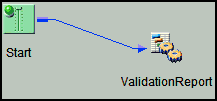
  2. In the Name field, type ValidationReport, and a brief description (optional) in the Description field and click Next.

    The Service Type dialog box opens.

  3. Select Class Name and enter com.ibi.agents.XDX12ValidationReportAgent and click Next.

    The Properties dialog box opens.

  4. Click Finish.

    The new Service object (ValidationReport) appears in the workspace.

  5. Select the Start object, right-click the ValidationReport object, and select Relation from the context menu.

    The Line Configuration dialog box opens.

  6. From the Event drop-down list, select OnCompletion and click OK.

    This option indicates that there are no conditions that affect the path, and that the path between the two objects will always be followed.

    A line appears between the objects to indicate that a relationship has been established.
  7. Drag and drop the File object from the toolbar to the workspace.

    The New File Object dialog box opens.

  8. In the Name field, type Write to Rpt Dir, and a brief description (optional) in the Description field and click Next.

    The File Type dialog box opens.

  9. From the Type drop-down list, select File Write and click Next.

    The Properties dialog box opens.
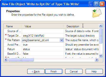
  10. For the Target Directory parameter, enter a location where error data will be written, for example, sreg(X12.ValidRpt).
  11. For the File Pattern parameter, enter sreg(basename)_rpt.xml.
  12. For the Return parameter, select status from the drop-down list and click Finish.

    The new File object (Write To Rpt Dir) appears in the workspace.

  13. Select the ValidationReport object, right-click the Write To Rpt Dir object, and select Relation from the context menu.

    The Line Configuration dialog box opens.

  14. From the Event drop-down list, select OnCompletion and click OK.

    A line appears between the objects to indicate that a relationship has been established.

  15. Drag and drop the End object from the toolbar to the workspace.

    The End Name and Description dialog box opens.

  16. In the Name field, type End_Rpt, and a brief description (optional) in the Description field and click Next.

    The End Name Schema dialog box opens.

  17. Since no schemas are used in this processing path (that is, the process flow will not be exposed as a web service), from the Schema drop-down list, select None and click Next.

    The Properties dialog box opens.

  18. Click Finish to accept the default values and close the dialog box.

    The new End_Rpt object appears in the workspace.

  19. Select the Write To Rpt Dir object, right-click the End_Rpt object, and select Relation from the drop-down list.

    The Line Configuration dialog box opens.

  20. From the Event drop-down list, select OnCompletion and click OK.

    A line appears between the objects to indicate that a relationship has been established.

  21. Drag and drop the Service object from the toolbar to the workspace.

    The New Service Object dialog box opens.

  22. In the Name field, type X12AckAgent, and a brief description (optional) in the Description field and click Next.

    The Service Type dialog box opens.

  23. Select Class Name and enter com.ibi.agents.XDX12AckAgent and click Next.

    The Properties dialog box opens. The configuration parameters for EDIX12AckAgent are displayed. The following table lists and describes the configuration parameters.

    Parameter

    Description

    Protocol

    Protocol on which to make acknowledgment copies. Select one of the following options from the drop-down list:

    • NONE
    • FILE

    Location

    Location for acknowledgment copies.

    End Tag

    The surrounding XML tag.

    Preemitter

    Determines whether the preemitter should be run on acknowledgment output.

    Error

    Determines whether to send an error.

    ISA Control Number

    Element location of ISA control number. Select one of the following locations from the drop-down list:

    • Input Document
    • _SReg(edi.ICN)

    GS Control Number

    Element location of GS control number. Select one of the following locations from the drop-down list:

    • Input Document
    • _SReg(edi.GCN)

    ST Control Number

    Element location of ST control number. Select one of the following locations from the drop-down list:

    • Input Document
    • _SReg(edi.MCN)

    Stream Acknowledgment

    Determines the level of acknowledgment information to return. Select one of the following acknowledgment levels from the drop-down list:

    • Group. Returns acknowledgment information at the Group level.
    • Interchange. Returns acknowledgment information at the Interchange level.
    • Transaction. Returns acknowledgment information at the Transaction level.

  24. Configure the available parameters according to your requirements.
  25. Click Finish.

    The new Service object (X12AckAgent) appears in the workspace.

  26. Select the Start object, right-click the X12AckAgent object, and select Relation from the context menu.

    The Line Configuration dialog box opens.

  27. From the Event drop-down list, select OnCompletion and click OK.

    A line appears between the objects to indicate that a relationship has been established.
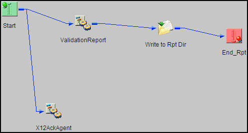
  28. Drag and drop the Set object from the toolbar to the workspace.

    The New Set Object dialog box opens.

  29. In the Name field, type SetAckStatus, and a brief description (optional) in the Description field and click Next.

    The Define Events dialog box opens.
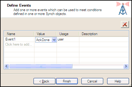
  30. In the first row of the Name column, type Event1.
  31. In the first row of the Name column, select AckDone from the drop-down list and click Finish.

    The new Set object appears in the workspace.

  32. Select the X12AckAgent object, right-click the SetAckStatus object, and select Relation from the context menu.

    The Line Configuration dialog box opens.

  33. From the Event drop-down list, select OnCompletion and click OK.

    A line appears between the objects to indicate that a relationship has been established.
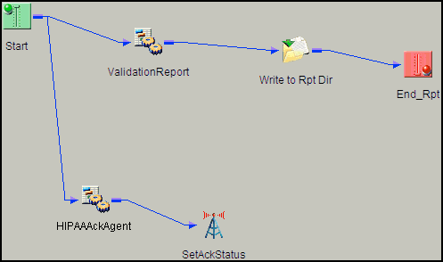
  34. Drag and drop the End object from the toolbar to the workspace.

    The End Name and Description dialog box opens.

  35. In the Name field, type End, and a brief description (optional) in the Description field and click Next.

    The End Name Schema dialog box opens.

  36. Since no schemas are used in this processing path (that is, the process flow will not be exposed as a web service), from the Schema drop-down list, select None and click Next.

    The Properties dialog box opens.

  37. Click Finish to accept the default values and close the dialog box.

    The new End_Success object appears in the workspace.

  38. Select the SetAckStatus object, right-click the End object, and select Relation from the drop-down list.

    The Line Configuration dialog box opens.

  39. From the Event drop-down list, select OnCompletion and click OK.

    A line appears between the objects to indicate that a relationship has been established.
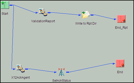
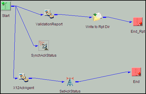
  40. Drag and drop the Sync object from the toolbar to the workspace.

    The New Sync Object dialog box opens.

  41. In the Name field, type SynchAckStatus, and a brief description (optional) in the Description field and click Next.

    The Sync Expression Builder dialog box opens.

  42. Click the first row of the Name column.

    Default values are entered in this row.

  43. In the first row of the Name column, select AckDone from the drop-down list and click Next.

    The Timeout dialog box opens.

  44. Click Finish.

    The new SynchAckStatus object appears in the workspace.

  45. Select the Start object, right-click the SynchAckStatus object, and select Relation from the context menu.

    The Line Configuration dialog box opens.

  46. From the Event drop-down list, select OnCompletion and click OK.

    This option indicates that there are no conditions that affect the path, and that the path between the two objects will always be followed.

    A line appears between the objects to indicate that a relationship has been established.
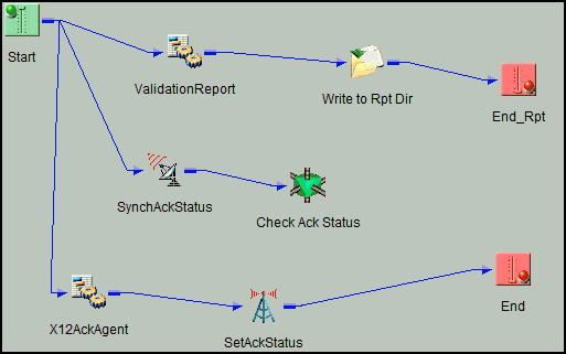
  47. Drag and drop the Decision Switch object from the toolbar to the workspace.

    The New Decision Switch Object dialog box opens.

  48. In the Name field, type Check Ack Status, and a brief description (optional) in the Description field and click Next.

    The Switch Expression dialog box opens.

  49. Type the following value in the field:
    sreg(edi.ackstatus)
  50. Click Next.

    The Switch Cases dialog box opens.
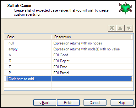
  51. In the Case Column, enter the following lines in separate rows:

    Case

    Description

    A

    EDI Good

    R

    EDI Reject

    E

    EDI Error

    P

    EDI Partial

  52. Click Finish.

    The new Decision Switch object appears in the workspace.

  53. Select the SyncAckStatus object, right-click the Check Ack Status object, and select Relation from the context menu.

    The Line Configuration dialog box opens.

  54. From the Event drop-down list, select OnCompletion and click OK.

    This option indicates that there are no conditions that affect the path, and that the path between the two objects will always be followed.

    A line appears between the objects to indicate that a relationship has been established.
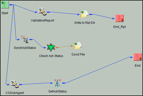
  55. Drag and drop the File object from the toolbar to the workspace.

    The New File Object dialog box opens.

  56. In the Name field, type Good File, and a brief description (optional) in the Description field and click Next.

    The File Type dialog box opens.

  57. Select File Write from the drop-down list and click Next.

    The Properties dialog box opens.

  58. For the Target Directory parameter, enter the following location where valid data will be written:
    sreg(X12.GoodOutput)
  59. For the File Pattern parameter, enter the following:
    sreg(basename)_*.xml
  60. For the Respect Transactionality parameter, select true from the drop-down list.
  61. Accept the default values for the remaining parameters and click Finish.

    The new File object (Good File) appears in the workspace.

  62. Select the Check Ack Status object, right-click the Good File object, and select Relation from the context menu.

    The Line Configuration dialog box opens.

  63. From the Event drop-down list, select OnCustom.
  64. In the Case of section, select case A (EDI Good).
  65. Click OK.

    A line appears between the objects to indicate that a relationship has been established.
  66. Drag and drop the File object from the toolbar to the workspace.

    The New File Object dialog box opens.

  67. In the Name field, type Bad File, and a brief description (optional) in the Description field.
  68. Click Next.

    The File Type dialog box opens.

  69. Select File Write from the drop-down list and click Next.

    The Properties dialog box opens.

  70. For the Target Directory parameter, enter the following location where valid data will be written:
    sreg(X12.BadOutput)
  71. For the File Pattern parameter, enter the following:
    sreg(basename)_*.xml
  72. For the Respect Transactionality parameter, select true from the drop-down list.
  73. Accept the default values for the remaining parameters.
  74. Click Finish.

    The new File object (Bad File) appears in the workspace.

  75. Select the Check Ack Status object, right-click the Bad File object, and select Relation from the context menu.

    The Line Configuration dialog box opens.

  76. From the Event drop-down list, select OnCustom.
  77. In the Case of section, select cases R (EDI Reject), E (EDI Error), and P (EDI Partial).
  78. Click OK.

    A line appears between the objects to indicate that a relationship has been established.
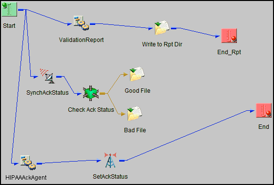
  79. Select the Good File object, right-click the End object, and select Relation from the drop-down list.

    The Line Configuration dialog box opens.

  80. From the Event drop-down list, select OnCompletion and click OK.
  81. Select the Bad File object, right-click the End object, and select Relation from the context menu.

    The Line Configuration dialog box opens.

  82. From the Event drop-down list, select OnCompletion and click OK.

    A line appears between the objects to indicate that a relationship has been established.
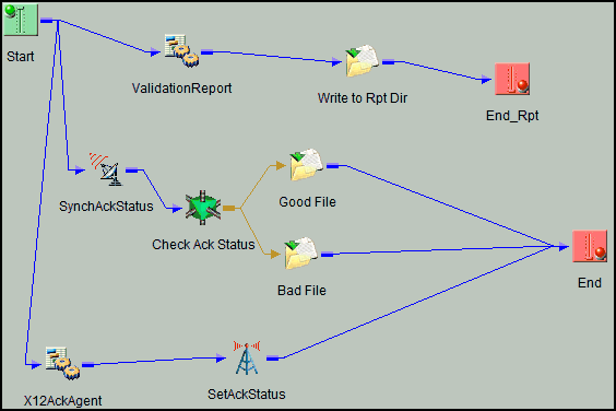
    The process flow is now complete.

  83. To save the process flow, right-click the X12toXML_pflow_AckRpt node in the left pane and select Save from the context menu.

    Now you need to validate the process flow and publish it to the Registry of the iWay Service Manager Administration Console for use in the route of a channel for outbound processing.

    Validating a process flow ensures that its structure is correct. Publishing a process flow makes it available in the Registry for use in a channel configuration. For instructions on validating and publishing the process flow, see the iWay Designer User's Guide.

  84. Close iWay Designer.

    Your next step is to add a new route to the Registry using the iWay Service Manager Administration Console and associate the process flow with it.


x
Procedure: How to Define a Route and Associate the Process Flow With the Route

To define a route and associate the process flow with It:

  1. From the Registry menu options in the iWay Service Manager Administration Console, click Routes.
  2. On the Route Definitions pane, click Add to add a route.
  3. On the New Route Definition pane, enter a name for the route and an optional description, as shown in the following table.

    Parameter

    Value

    Name *

    EDItoXML_Route

    Description

    This route will invoke the X12 to XML validation process. The outcome of this process will place valid X12 transformed data in your valid inbound folder. Invalid X12 transformed data will be routed to its appropriate folder. A validation report will also be generated and sent to its appropriate folder.

  4. Click Finish.
  5. On the Construct Route pane, click Add.

    You are prompted for the type of component to associate with the route.

  6. Select Process and click Next.
  7. The next pane prompts you to select a process. Select the process flow you created earlier with iWay Designer, x12toXML_pflow_AckRpt, and click Finish.

    The route, with its associated process flow, has been successfully defined.


x
Defining the Outlets

An outlet defines how a message leaves a channel. An emitter is a transport protocol that sends a document to its recipient. In the sample configuration, we will use a File emitter. For details on supported protocols, see the iWay Service Manager Protocol Guide.

For the channel in this example, you will add one emitter to the Registry. Then you will define one outlet and associate the emitter with this outlet.

When you associate the outlet with the channel in later steps, you will apply a condition to dynamically direct the flow of the output document based on its content.

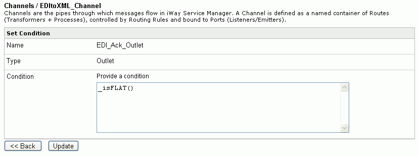
In the example, you will add an emitter for the acknowledgement data. In the example, the data for the functional acknowledgement (transaction 997) is in EDI flat file (non-XML) format. When you add the acknowledgement outlet to the channel, you will set the condition _isFLAT(). This condition tests the output data for flat file (non-XML) format. If the data is in flat file (non-XML) format, it is routed to the specified destination.


x
Procedure: How to Add an Emitter for Acknowledgement Output
  1. On the Emitters pane, click Add to add another emitter. The next pane prompts you for the emitter type.
  2. For this example, select File from the drop-down list and click Next.

    The configuration parameters pane opens.

  3. Supply configuration parameters for the second File emitter as follows, then click Next.

    Parameter

    Value

    Destination *

    sreg(X12.Ack)/SREG(basename)*.txt

    This value is the directory where the acknowledgement output is placed. You can use an extension other than .txt, for example, .edi or .data.

    sreg(X12.Ack) is a special register value that uses a defined directory in which output files are stored after transformation.

    Make sure that you have created this directory; otherwise, errors will occur during deployment.

    On output, an asterisk (*) in the destination file name is replaced by a date and time stamp. For details on the special register (SREG) used in the preceding file name, see the iWay Service Manager User's Guide.

    Create Directory

    false

  4. On the Emitters pane, enter the name of the new emitter and an optional description, as shown in the following table. Then click Finish to add the emitter.

    Parameter

    Value

    Name *

    Ack_Out_Emitter

    Description

    Emitter for acknowledgement output for EDI.


x
Procedure: How to Define an Outlet for Acknowledgement Output
  1. From the Registry menu options, select Outlets.
  2. On the Outlet Definitions pane, click Add to add an outlet.
  3. On the New Outlet Definition pane, enter the name of the new outlet and an optional description, as shown in the following table. Then click Finish to add the outlet.

    Parameter

    Value

    Name *

    EDI_Ack_Outlet

    Description

    Acknowledgement outlet for EDI.

  4. On the Construct Outlet pane, click Add to associate the acknowledgement emitter with the acknowledgement outlet. The next pane prompts you for the component type.
  5. Select Emitter and click Next.

    The next pane prompts you to select an emitter.

  6. Select Ack_Out_Emitter, which is the acknowledgement emitter you added earlier, and click Finish.

    Now you have defined the two outlets.


x
Defining a Channel

Now that you have defined the inlet, route, and outlets for the channel, you are ready to add the channel to the Registry and associate the conduits with it.


x
Procedure: How to Define a Channel
  1. From the Registry menu options, select Channels under Conduits.
  2. On the Channel Definitions pane, click Add to add a channel.
  3. On the New Channel Definition pane, enter the name of the new channel and an optional description, as shown in the following table. Then click Finish to add the channel.

    Parameter

    Value

    Name *

    EDItoXML_Channel

    Description

    Channel for EDI to XML inbound processing.

  4. On the Construct Channel pane, click Add to associate the inlet, route, and outlets defined previously with the channel.

    You are prompted to associate components with the channel.

  5. Select Inlet and click Next. The next pane prompts you to select an inlet.
  6. Select EDItoXML_Inlet, which is the inlet you defined earlier, and click Finish.

    The inlet is added to the channel. Now you need to associate the route defined earlier with the channel.

  7. On the Construct Channel pane, click Add.

    The next pane prompts you for the component type.

  8. Select Route and click Next.

    On the next pane, you are prompted to select a route.

  9. Select EDItoXML_Route, which is the route created earlier, and click Finish.
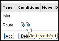
  10. On the Construct Channel pane, click the minus sign (-) under Conditions next to the name of the route to set it as the default.

  11. On the Construct Channel pane, click Add to add the outlets.
  12. On the next pane, select Outlet and click Next.
  13. Select the outlet defined earlier, EDI_Ack_Outlet and click Finish.
  14. To set a condition for the EDI_Ack_Outlet, on the Construct Channel pane, click the plus sign (+) under Conditions for the EDI_Ack_Outlet.

    The Set Condition pane opens.

  15. In the Condition input field, enter _isFLAT(), and click Update.

    This condition tests the output data for EDI flat file (non-XML) format. If the data is in EDI flat file (non-XML) format, it is routed to the destination specified when you added the emitter for acknowledgement output.


x
Procedure: How to Add a Special Register Set to the Channel
  1. From the Registry menu options, select Channels.

    The Channel Definitions pane opens.

  2. Click the link in the Regs column for EDItoXML_Channel.
  3. On the next pane, which prompts you to add special register (SREG) sets, click Add to add the SREG set to the channel.
  4. On the next pane, select X12, which is the name of the SREG set you created previously, and click Finish.


x
Procedure: How to Add the Ebix to the Channel
  1. From the Registry menu options, select Channels.

    The Channel Definitions pane opens.

  2. Click the link in the Ebix column for the EDItoXML_Channel.
  3. On the next pane, which prompts you to add Ebix components, click Add to add the Ebix to the channel.
  4. On the next pane, select EDI_4050, which is the name of the Ebix you added previously, and click Finish.

    Now that you have associated all the components with the channel, you are ready to build it.


x
Procedure: How to Build the Channel
  1. From the Registry menu options on the left pane, select Channels under Conduits.
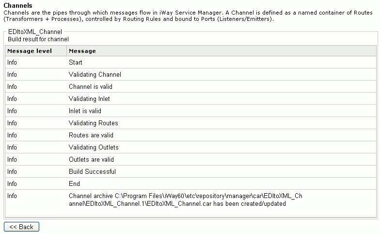
  2. On the Channel Definitions pane, select the channel defined previously, EDItoXML_Channel, and click Build.

    The results of the build are displayed on the right pane.

  3. Review the results of your build and then click Back.

    If an error or errors are displayed in the Message column, take the appropriate action as instructed.


x
Procedure: How to Deploy the Channel

Deployment is the mechanism by which a channel moves from being stored in the Registry to becoming active in iWay Service Manager. For more information on deployment, see the iWay Service Manager User's Guide.

  1. Select the Deployments option in the blue shaded area below the iWay Service Manager banner.
  2. On the Channel Management pane, click Deploy.
  3. On the Available Channels pane, select the channel you defined previously, EDItoXML_Channel, and click Deploy.

    The Channel Management pane reopens.

  4. Select EDItoXML_Channel and click Start.

    The red X under Status changes to a green check mark to indicate that the channel has been started. If an error or errors are displayed, take the appropriate action as instructed.


x
Procedure: How to Verify the Channel

To make sure that the channel is working as expected, perform the following steps:

  1. Place an EDI document as test data in the C:\File_in directory. This is the path in which EDI messages are received, which you specified for the listener associated with the inlet for the channel.

    The following table contains links to EDI files that are attached to this PDF and can be used to verify your channel.

    EDI 810 Invoice

    EDI 850 Purchase Order

    EDI 856 Advanced Ship Notice

    .

    810.x12.txt

    .

    850.x12.txt

    .

    856.x12.txt

    Note: For file association compatibility only, each EDI file that is attached to this PDF has been renamed to include a .txt extension. However, please note that the actual EDI output file that is placed in the C:\File_in directory will not carry a .txt extension.

  2. Check for the XML file and the functional acknowledgement in the C:\File_out\EDI directory. This is the destination path you specified for the emitters associated with the outlets for the channel. The listener will detect the presence of the file in the input directory, and the copy service will copy it to the output directory, replacing the asterisk in the file name with a time stamp.

    For example, if you specified the destination file name for the XML emitter as _SREG(basename)_*.xml per the configuration example, an EDI input file named X12856C001_4050.x12 is named _X12856C001_4050_2008-03-03T19_33_26.684Z.xml on output.

    The following table contains links to sample XML output files that are attached to this PDF and can be used to verify your output.

    X12 810 4010

    X12 850 4010

    X12 856 4010

    .

    810.xml

    .

    850.xml

    .

    856.xml

    The following table contains links to sample functional acknowledgement documents that are attached to this PDF and can be used to verify your output.

    810.997

    850.997

    856.997

    .

    810.997.txt

    .

    850.997.txt

    .

    856.997.txt

    Note: For file association compatibility only, each functional acknowledgement document that is attached to this PDF has been renamed to include a .txt extension. However, please note that the actual functional acknowledgement document that is placed in the C:\File_out\EDI directory will not carry a .txt extension.


x
Reusing Your Channel Configuration

Using the Archive Manager feature of iWay Service Manager, you can archive your channel configuration with its associated components and import them into another Registry. They will then be available from that Registry for modification or reuse.

For details on this feature, see the iWay Service Manager User's Guide.


iWay Software